1-11
UX-V10GN
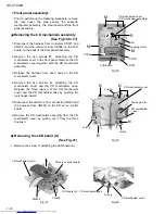
Prior to performing the following procedure, remove
the CD mechanism assembly.
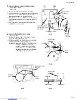
Remove the screw P attaching the LED board (B).
1.
Removing the LED board (B) (See Fig.22)
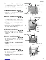
Prior to performing the following procedure, remove
the LCD board assembly.
Remove the eight screws T attaching the operation
switch board.
1.
Removing the operation switch board
(See Fig.24)
Release the hook i fixing the CD door switch board
to the CD mechanism cover.
1.
Removing the CD door switch board
(See Fig.22)
Prior to performing the following procedure, remove
the CD mechanism assembly and the LED board (A)
/ (B).
Remove the two screws Q attaching the CD servo
control board.
Pull out the CD servo control board in the direction of
the arrow by releasing the two joints j.
1.
2.
Removing the CD servo control board
(See Fig.22)
Remove the belt and the two screws R attaching the
loading motor on the back of the front panel
assembly.
1.
Removing the loading motor
(See Fig.18)
Prior to performing the following procedure, remove
the CD mechanism cover (CD mechanism
assembly).
Remove the two screws S attaching the LCD board
assembly.
Disconnect connector CN781 on the LCD board
assembly from the operation switch board.
1.
2.
Removing the LCD board assembly
(See Fig.23)
Fig.18
Fig.22
Fig.23
Fig.24
Joint j
LCD board (A)
CD servo control
board
CD door switch board
Hook i
LCD board (B)
P
Q
O
Q
M
M
M
R
CD mechanism cover
(CD mechanism assembly)
LCD board
CN766
CN721
CN722
Loading motor
Belt
LCD board assembly
Operation switch board
S
CN781
T
T
T
Operation switch board
Summary of Contents for UX-V10GN
Page 32: ...1 32 UX V10GN LC75342 ...


