


(No.MB057)1-13
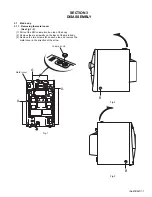
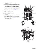
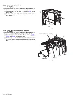
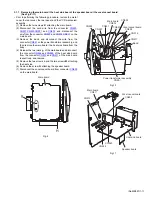
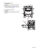
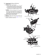
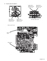
3.1.9 Removing the front panel assembly
(See Fig.13,14)
• Prior to performing the following procedure, remove the metal
cover, the rear cover, the rear panel, and the VCD mechanism
assembly.
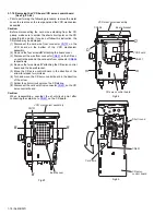
(1) Remove the two screws
Q
on each side. Release the two
joints
h
on the both sides and lift the front panel assembly
to release the joint
j
.
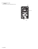
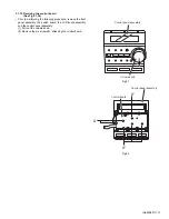
(2) Disconnect the card wire from the connector
CN900
,
CN901
,
CN930
,
CN931
and
CN932
on the main board.
Fig.13
Fig.14
Q
h
Front panel assembly
Q
h
j
Front panel assembly
CN932
CN931
CN930
CN900
CN901
Main board