background image

12

EXIT

CHROMA

MENU

PHASE

BRIGHT

CONTRAST

VOLUME/SELECT


< MENU >

4

APERTURE

:   00

ADJ. BAR POSI.

: LOWER

COLOR TEMP.

: 6500

COLOR SYSTEM

: AUTO

COMPO. LEVEL

:   00

RUSH DELAY

: STD.

Menu items

Purpose

 Setting range

APERTURE

Picture aperture level

ADJ.BAR POSI.

Volume bar position

COLOR TEMP.

Color temperature of white
balance

COLOR SYSTEM

Color system

COMPO. LEVEL

Component level

RUSH DELAY

Delay time

Front panel

Function                     

Contents

button

displayed

+

Increase (to max. value)

4

Forward the setting value

Decrease (to min. value)

1

Reverse the setting value

VOLUME/

SELECT (–)

VOLUME/

SELECT (+)

Front panel

Function                     

Contents

button

displayed

CHROMA/

Forward selection mark (

4

)

PHASE

CONTRAST/

Reverse selection mark (

4

)

BRIGHT

Front panel

Function                     

Contents

button

displayed

MENU

EXIT

Quit (or Release) the <MENU>
screen

1

2

3

4

HOW TO USE THE MENU FUNCTIONS

• APERTURE

• COLOR SYSTEM

• ADJ. BAR POSI.

• COMPO. LEVEL

• COLOR TEMP.

• RUSH DELAY

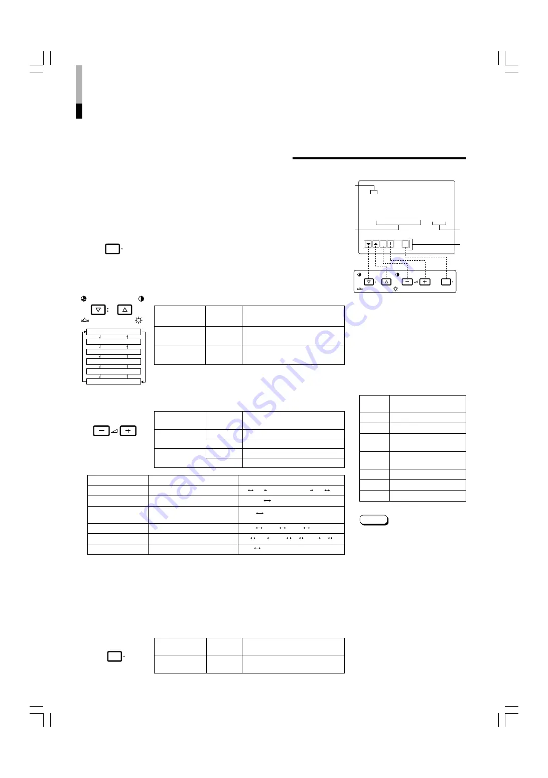
You can set the following menu items.
Set them depending on your needs.

1. Press the MENU button.

The <MENU> screen is displayed.
* The on-screen display goes off automatically after about five

minutes with operation performed.

2. Press the CHROMA/PHASE or CONTRAST/BRIGHT

button to select MENU items.

A selection mark (

4

) is put next to the selected item.

APERTURE

ADJ. BAR POSI.

COLOR TEMP.

COLOR  SYSTEM

COMPO. LEVEL

RUSH DELAY

3. Press the VOLUME/SELECT buttons to set.

4. If you want to set the other menu items, repeat

procedures 2 and 3.

5. Press the MENU button to quit.

1

 Selection mark (

4

): Indicates the

menu item you select.

2

 Menu item: Menu items you can

select.

3

 Setting display: Indicates the current

settings (value).

4

 Function display: The functions of

the front panel buttons (5 buttons on
the left) correspond to the function
displayed.

<MENU> screen

<Front panel buttons>

Function

Contents

displayed

Forward the menu item.

Reverse the menu item.

Lower the adjustment
value. (to the minimum)

+

Raise the adjustment

value. (to the maximum)

4

Forward the setting value.

1

Reverse the setting value.

EXIT

Exits the <MENU> screen.

DISPLAY AND SELECTION IN THE <MENU>
SCREEN MODE (SETTING)

MENU

CHROMA

PHASE

BRIGHT

CONTRAST

VOLUME/SELECT

MENU

LOWER       UPPER

6500       9300

AUTO       NTSC       AUTO       PAL

STD.       SLOW

* For normal use, leave the COLOR SYSTEM setting to AUTO.

If reception is unsatisfactory in AUTO position, set it to the appropriate color system mode (NTSC or PAL).

* COMPO. LEVEL is displayed only with component serial digital (SDI) input. (Shown with INPUT-C and

INPUT-D except for RGB input.)

00     +01                                  +39     +40

• • • • • • • • • • • •

– 40     – 39       – 01    00    +1       +9    +10

• • 

• •

Note:

RUSH DELAY sets the delay between
the time the power switch is pressed
and the time power is actually
supplied to the monitor’s circuits.
STD.

: Power turns on approximately

1 second after the power
switch is pressed.

SLOW : Power turns on approximately

3 seconds after the power
switch is pressed.

* When turning on multiple Color-

Video Monitors simultaneously, it is
recommended to use STD. or SLOW
settings to reduce the rush current
of the entire system.

LCT1025-002B-H(EN)4.p65

07.11.8, 6:27 PM

14

Summary of Contents for TM-H1750CG

Page 1: ...CG TM H1750CG COLOR VIDEO MONITOR ESPAÑOL ITALIANO FRANÇAIS DEUTSCH ENGLISH 中文 POWER CHROMA MENU ASPECT INPUT SELECT UNDER SCAN COLOR OFF BLUE CHECK PHASE TM H1950CG BRIGHT CONTRAST VOLUME SELECT A B SLOT C D LCT1025 003A H TM H1950CG shown Gezeigtes Modell ist TM H1950CG TM H1950CG montré Modello TM H1950CG Muestra de TM H1950CG TM H1950CG 圖 TM H1750CG 11 8 2007 17 57 Page 1 Adobe PageMaker 6 5C ...

Page 2: ...TM H1750CG 11 8 2007 17 57 Page 2 Adobe PageMaker 6 5C PPC ...

Page 3: ...ONITOR TM H1950CG TM H1750CG Thank you for purchasing this JVC color video monitor Before using it read and follow all instructions carefully to take full advantage of the monitor s capabilities LCT1025 002B H EN 4 p65 07 11 8 6 27 PM 3 ...

Page 4: ...qualified service personnel to dispose of this unit This monitor is equipped with a 3 blade grounding type plug to satisfy FCC rule If you are unable to insert the plug into the outlet contact your electrician Machine Noise Information Ordinance 3 GSGV January 18 1991 The sound pressure level at the operator position is equal or less than 70 dB A according to ISO 7779 Improper operations in partic...

Page 5: ...alled it can be easily affected by surrounding magnetic fields which can generate irregular color on the screen When it is difficult to eradicate degauss from outside using a degausser etc 3 Fuse POWER CONNECTION The power supply voltage rating of this product is AC 120 V For U S A and Canada only and AC 230 V For European countries or United Kingdom the power cord attached conforms to the followi...

Page 6: ...e button again to restore the normal image When selected this button lights Aspect button ASPECT Press this button to change the aspect ratio from 4 3 to 16 9 Input A VIDEO button INPUT SELECT A Selects the video and audio signals input to the VIDEO A and AUDIO A q terminals on the rear panel The button lights when selected Input B VIDEOY C button INPUT SELECT B Selects the video and audio signals...

Page 7: ...ridge connected The input signal is automatically terminated if a cable is not connected to the OUT terminal IN Y C separated S video video signal input terminal OUT Bridge connected Y C separated S video signal output terminal Notes For corresponding audio signals use the AUDIO B terminals w When both VIDEO B terminals are connected input at the same time the Y C terminal has priority Also refer ...

Page 8: ...United Kingdom For Europe 23 Power cord Connects the provided power cord 120 V AC or 230 V AC 50 Hz 60 Hz to the AC IN connector r Caution In North America USA and Canada this monitor comes with one power cable In Europe and the United Kingdom two power cables are provided one for use in continental European countries and the other for the UK Be sure to use the power cable that is appropriate for ...

Page 9: ...DDED AUDIO channel selection The factory setting for the EMBEDDED AUDIO channel selection is as follows the CH1 terminal 1ch the CH2 terminal 2ch It is necessary to change settings with the DIP switches on the input card to select other channels for the terminals Refer to the input card instructions SWITCHED OUT terminal 1 line Re clocks and outputs the input signal currently selected NOTE The sig...

Page 10: ...r s rear panel 5 Secure the Input Card by replacing the screws removed in Procedure 2 VIDEO A REMOTE SLOT VIDEO B IN OUT IN IN OUT Y C INSTALLINGTHE INPUT CARD Slot cover Fit the board to the guide rails Rear side of the TM H1950CG color video monitor Knob Input card the illustration shown is of the IF C01COMG Guide rails Knob NOTE Do not touch the terminal connected to the monitor or board patter...

Page 11: ...rd Holder prevents the AC power cord from being accidentally disconnected from the AC inlet The Power Cord Holder consists of two parts a case and cover Press the cover until it clicks Hold until it clicks Caution A different plug shape will result in the cover being attached to a different position Check to make sure the plug doesn t pull out after the cover is attached Note To disconnect the pow...

Page 12: ...OMA PHASE button and CONTRAST BRIGHT button alternately while the item is shown on screen restores the previous status When no item is shown on screen CHROMA and CONTRAST have priority Screen indication will disappear about 10 seconds after operating The on screen display goes off when you press MENU button About the STATUS indication With the COLOR SYSTEM setting set to AUTO mode when you turn on...

Page 13: ...nly when an NTSC signal is input Press the PHASE button to adjust the phase so that the two blue bars at the center of the screen have the same brightness 5 Only when an NTSC signal is input Repeat procedures 3 and 4 for the adjustment so that all four blue bars on the screen have the same brightness When you have finished making the adjustment press the BLUE CHECK button to deactivate Initializin...

Page 14: ... items repeat procedures 2 and 3 5 Press the MENU button to quit 1 Selection mark 4 Indicates the menu item you select 2 Menu item Menu items you can select 3 Setting display Indicates the current settings value 4 Function display The functions of the front panel buttons 5 buttons on the left correspond to the function displayed MENU screen Front panel buttons Function Contents displayed Forward t...

Page 15: ...value EXIT Exit the MENU screen DRV Selects DRIVE adjustment CUTO Selects CUT OFF adjustment RB Adjusts red and blue signal level RGB Adjusts red green and blue signal level Turns the ON SCREEN display on or off This DISP function is effective only in the DRIVE or CUT OFF adjustment mode Front panel Function Contents button displayed CHROMA Forward selection mark 4 PHASE CONTRAST Reverse selection...

Page 16: ...E button Then set the CONTROL LOCK function to OFF Even when the CONTROL LOCK function is set to ON the following operations are available Power Switch operation Volume control with the VOLUME SELECT buttons Display or disappear of the SET UP MENU screen The STATUS DISPLAY function can be set to display ON or not display OFF the present color system when the power is turned on or the input signal ...

Page 17: ... items and the volume level to their factory set initial values 1 Press the Power switch to turn the power OFF activate the standby mode The SET UP MENU RESET screen is displayed Initial settings SET UP MENU RESET screen 2 While pressing both MENU button and CHROMA PHASE button press the Power switch to turn the power ON 3 Setting Initialization is required Initialization is not required Press the...

Page 18: ...e input IN and output OUT terminals on the monitor to separate video components For example if both terminals are connected to the same VCR resonance may occur except during playback This is caused by the same video signal looping between the VCRs and is not a malfunction Select the video input signal INPUT A VIDEO or INPUT B VIDEO Y C with the INPUT SELECT buttons on the front panel When both VID...

Page 19: ... B VIDEO B IN OUT IN IN IN OUT OUT IN OUT Y C OUT Video Camera Video Monitor VCR Y C S video Y C S video signal cable Audio Audio signal cable Audio Audio signal cable Y C S video Y C S video signal cable Video Monitor VCR Signal Flow 17 LCT1025 002B H EN 4 p65 07 11 8 6 27 PM 19 ...

Page 20: ...witches input by short circuiting a specified signal line in INPUT A to D 1 pin control Switches between INPUT A and INPUT B only with the 2nd pin of the D sub connector In this case INPUT C and INPUT D cannot be selected OFF INPUT A ON INPUT B NOTES When more than two terminals are selected short circuited from INPUT A through INPUT D under the MAKE system the signal input is prioritized alphabet...

Page 21: ...on See page 10 Connect the audio signal cable firmly See pags 16 and 17 Move the device away from the monitor until the picture stabilizes Set COLOR SYSTEM in the MENU screen to AUTO See page 12 Set each picture control to the standard setting See page 10 Press the COLOR OFF button and BLUE CHECK button to adjust See page 11 Move the device away from the monitor and turn the monitor s power off Wa...

Page 22: ...L bridge connection possible auto termination AUDIO A 1 line monaural RCA pin x 2 0 5 V rms high impedance bridge connection possible AUDIO B 1 line monaural RCA pin x 2 0 5 V rms high impedance bridge connection possible REMOTE Point of contact connection 1 line D sub connector 15 pin 3 line Audio power output 1 W Built in speaker 8 cm round x 1 impedance of 8 Ω Environmental conditions Operation...

Page 23: ...ew Side View Unit mm inch 21 POWER CHROMA MENU ASPECT INPUT SELECT SLOT UNDER SCAN COLOR OFF BLUE CHECK PHASE TM H1750CG BRIGHT CONTRAST VOLUME SELECT A B C D 395 15 5 8 418 16 1 2 407 16 1 8 68 2 3 4 286 11 3 8 3 1 8 3 1 8 336 3 13 1 4 288 11 3 8 ø20 7 8 256 10 1 8 334 13 1 4 175 7 1 5 1 16 Front View Side View TM H1950CG TM H1750CG Unit mm inch Asterisks are used to indicate front panel dimensio...

Page 24: ...UT D SDI 2 You can use the front panel buttons or do it via external control When INPUT A or INPUT B is selected this terminal outputs the signals last selected In the standby mode signals from the SDI 1 connector are output APPENDIX CONNECTION EXAMPLES FORTHE SDI INPUT CARD Pin No Signal 1 GND Y 2 GND C 3 Y 4 C Y C Mini DIN 4 pin terminal specification IN Y C OUT 2 1 2 1 4 3 4 3 22 LCT1025 002B H...

Page 25: ...1107STH MW MT 2007 Victor Company of Japan Limited TM H1950CG TM H1750CG TM H1750CG 11 8 2007 18 01 Page 25 Adobe PageMaker 6 5C PPC ...

Reviews: