


1-6
TM-A170G
ENGLISH
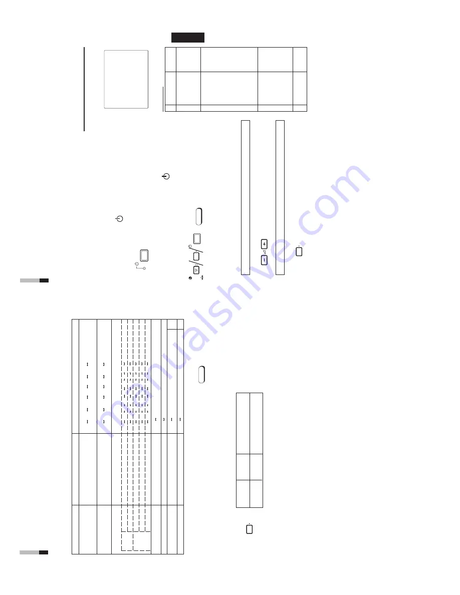
Functions (Items)
Initialization
(setting)
SHARPNESS
00
COLOR
TEMP
.
6500
COLOR SYSTEM
AUT
O
ASPECT
RA
TIO
4 – 3
H. POSITION
00
V
. POSITION
00
WHITE BALANCE
R. CUT OFF
00
G.
CUT
OFF
00
B.
CUT
O
FF
00
R. DRIVE
00
B. DRIVE
00
CONTROL
LOCK
OFF
ST
A
TUS DISPLA
Y
O
N
INPUT
REMOTE
OFF
ASPECT
REMOTE
OFF
CHROMA
0
0
PHASE
00
CONTRAST
00
BRIGHT
00
VOLUME
20
<SET–UP
MENU>
RESET
Are you sure ?
“Y
es”
then
<+>
“No”
then
<MENU>
Sorts
<MENU> screen
<SET-UP
MENU> screen
Volu
me
HOW TO INITIALIZE THE
SETTING
SCREEN DISPLA
Y AND SELECTIONS IN THE
<SET
-UP MENU> RESET MODE
Y
ou can set <MENU> and <SET
-UP
MENU> screen items, picture adjustment items and
the volume level to their factory-set (initial) values.
1. Press the Power (
) switch to turn the power
OFF (activate the standby mode).
The <SET
-UP
MENU> RESET
screen is displayed.
Initial settings
<SET
-UP
MENU> RESET
screen
2
.
While pressing both MENU button and
CHROMA/
PHASE
button,
press the Power (
)
switch to turn
the power ON.
3. Setting
Initialization is required.
Initialization is not required.
Press the VOLUME/SELECT [+] button.
* Initialization is completed, and the <SET
-UP
MENU>
RESET
screen
disappears.
Press the MENU button.
* Initialization is aborted, and the <SET
-UP
MENU>
RESET
screen
disappears.
●
The <SET
-UP
MENU> RESET
screen will not be
displayed if the MENU or CHROMA/PHASE buttons are
pressed for a very short time. Keep pressing them until
the display screen appears.
Note:
PO
WER
MENU
CHR
OMA
PHASE
PO
WER
MENU
V
O
LUME/SELECT
Picture adjustment
11
10
Set-up menu items
Purpose
Settings
H. POSITION
Adjusts the horizontal position of the
screen (+: Horizontal position shifts
to the right/-: Horizontal position shifts to
the left)
V
. POSITION
Adjusts the vertical position of the screen
(+: V
e
rtical position moves up/-: V
e
rtical
position moves down)
WHITE BALANCE
Adjusts the white balance.
Selects the drive (DR
V
) or cut of
f (CUT
O) adjustment.
The selected
setting screen is shown. Select the function display for adjustment.
DRIVE
R. DRIVE
Adjusts red level.
B. DRIVE
Adjusts blue level.
CUT
OFF
R.
CUT
OFF
Adjusts red cut of
f.
G.
CUT
OFF
Adjusts green cut of
f.
B.
CUT
OFF
Adjusts blue cut of
f.
CONTROL
LOCK
Sets the operation buttons on the front
panel to control lock mode.
ST
A
TUS
DISPLA
Y
Sets the status display of the color system.
INPUT
REMOTE
Sets external control of input selection
*1
(INPUT
A
/B).
ASPECT
REMOTE
Sets external control of the aspect ratio.
*1
4. T
o set the other set-up menu items, repeat the
procedures 2 and 3.
5. Press the MENU button to quit.
Notes:
●
When
the
CONTROL
LOCK
function
is set to ON, pressing operation
buttons on the front panel will display
the
message
“CONTROL
LOCK
ON!”
on the screen for about 3 seconds.
●
The
CONTROL
LOCK
function
is
maintained even when the power is
turned of
f.
●
T
o
turn of
f the CONTROL
LOCK
function, while holding the MENU
button press the CHROMA/PHASE
button.
Then
set
the
CONTROL
LOCK function to OFF
.
●
Even
when
the
CONTROL
LOCK
function is set to ON, the following
operations are available:
–
Power Switch operation
–
V
olume control with the VOLUME/
SELECT
buttons
–
D
isplay or disappear of the <SET
-
UP
MENU>
screen.
●
The ST
A
TUS DISPLA
Y
function can
be set to display (ON) or not display
(OFF) the present color system when
the power is turned on or the input
signal is changed. Refer to page 7 for
more information.
●
When INPUT REMOTE is activated
(ON),
and
any
one
of
the
INPUT
A
and B buttons is pressed, “REMOTE
ON!” appears on screen for about 3
seconds.
●
T
o
enable external control (the INPUT
or
ASPECT
RA
T
IO function), set
INPUT
REMOTE
or
ASPECT
REMOTE to ON.
Front panel
Function
Contents
button
displayed
MENU
EXIT
Quits (or Releases) the <MENU>
screen
MENU
–
5 • • •
–
01
00
+
1
• • •
+
5
–
5 • • •
–
01
00
+
1
• • •
+
5
OFF
ON
OFF
ON
*1 Refer to HOW
T
O USE EXTERNAL
CONTROL
on page 14 for more details.
–
20
–1
9
–
01 00
+
01
+
19
+
20
• •
• •
HOW TO USE THE MENU
FUNCTIONS
(cont’d)
OFF
ON
–
20
–1
9
–
01 00
+
01
+
19
+
20
• •
• •
–
20
–1
9
–
01 00
+
01
+
19
+
20
• •
• •
–
20
–1
9
–
01 00
+
01
+
19
+
20
• •
• •
–
20
–1
9
–
01 00
+
01
+
19
+
20
• •
• •
OFF
ON
Summary of Contents for TM-A170
Page 11: ...1 11 TM A170G MEMO ...