


7
MENU
VOLUME/SELECT
–
+
MENU
PHASE
CHROMA
BRIGHT CONTRAST
MENU
VOLUME/SELECT
–
+
EXIT
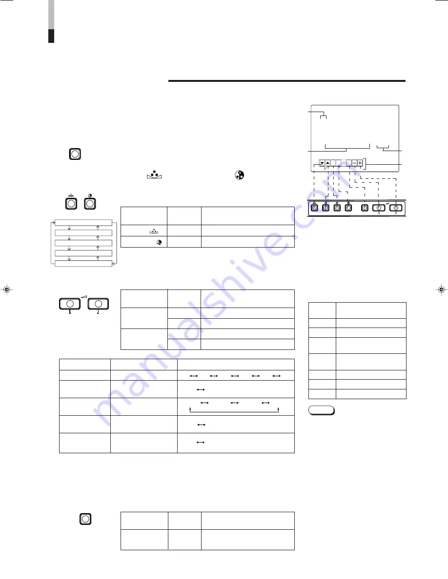
< MENU >
‰
SHARPNESS
: 00
COLOR TEMP.
: 6500
COLOR SYSTEM
: AUTO
ASPECT RATIO
: 4–3
BRIGHTNESS P.S.
: OFF
Menu items
Purpose
Setting range
SHARPNESS
Picture sharpness
COLOR TEMP.
Color temperature of
white balance
COLOR
Color system
SYSTEM
ASPECT RATIO
Aspect ratio
BRIGHTNESS
Brightness Peak
P.S.
Suppressor function
AUTO NTSC AUTO PAL
00 +1 +2 +3 +4 +5
Front panel
Function
Contents
button
displayed
+
Increase (to max. value)
3
Advance the setting value
–
Decrease (to min. value)
2
Reverse the setting value
VOLUME/
SELECT (–)
VOLUME/
SELECT (+)
Front panel
Function
Contents
button
displayed
PHASE (
)
∞
Advance selection mark (
3
)
CHROMA ( )
5
Reverse selection mark (
3
)
Front panel
Function
Contents
button
displayed
MENU
EXIT
Quit (or Release) the <MENU>
screen
1
2
3
4
HOW TO USE THE MENU FUNCTIONS
• SHARPNESS
• ASPECT RATIO
• COLOR TEMP.
• BRIGHTNESS P.S.
• COLOR SYSTEM
You can set the following menu items.
Set them depending on your needs.
1. Press the MENU button.
The <MENU> screen is displayed.
2. Press the PHASE (
) or CHROMA (
) button
to select MENU items.
A selection mark (
3
) is put next to the selected item.
SHARPNESS
COLOR TEMP.
COLOR SYSTEM
ASPECT RATIO
BRIGHTNESS P.S.
3. Press the VOLUME/SELECT button to set.
* Normally set the COLOR SYSTEM to the AUTO mode. If reception in the AUTO mode is not good,
set it to the exclusive mode (NTSC or PAL) corresponding to the received color system.
4. If you want to set the other menu items, repeat
procedures 2 and 3.
5. Press the MENU button to quit.
1
Selection mark (
3
3
3
3
3
): Indicates the
menu item you select.
2
Menu item: Menu items you can
select.
3
Setting display: Indicates the
current settings (value).
4
Function display: The functions of
the front panel buttons (7 buttons on
the left.) correspond to the function
displayed.
Notes:
●
BRIGHTNESS P.S. (or B.P.S.) stands for
Brightness Peak Suppressor. This function
is used to suppress (cut) the white peak
portion of the picture, so as to reduce the
picture's burning on the screen (cathode
ray tube).
●
When the BRIGHTNESS P.S. (or B.P.S.)
function is ON, the suppressed white peak
portion (for example, the lit part of a
fluorescent lamp) seems to be blurred.
If required, lower the setting for the B.P.S.
LEVEL in the <SET- UP MENU> screen
mode, or turn off the BRIGHTNESS P.S.
function.
●
When the screen aspect ratio is set to 16-9
(16:9) the picture will be vertically reduced.
●
When setting value of ASPECT RATIO or
BRIGHTNESS P.S. is set to REMOTE,
REMOTE SELECT is activated in the
<SET- UP MENU> mode, change the
setting in this case. When required, use the
external control function or turn off the
REMOTE SELECT setting.
<MENU> screen
<Front panel button>
Function
Contens
displayed
∞
Advance the menu item.
5
Reverse the menu item.
–
Lower the adjustment
value. (to the minimum)
+
Raise the adjustment
value. (to the maximum)
3
Advance the setting value.
2
Reverse the setting value.
EXIT
Exits the <MENU> screen.
DISPLAY AND SELECTION IN THE <MENU> SCREEN
MODE (SETTING)
PHASE
CHROMA
6500 9300
4 – 3 16 – 9
OFF ON


