background image

EN

 9

Connections & Installation

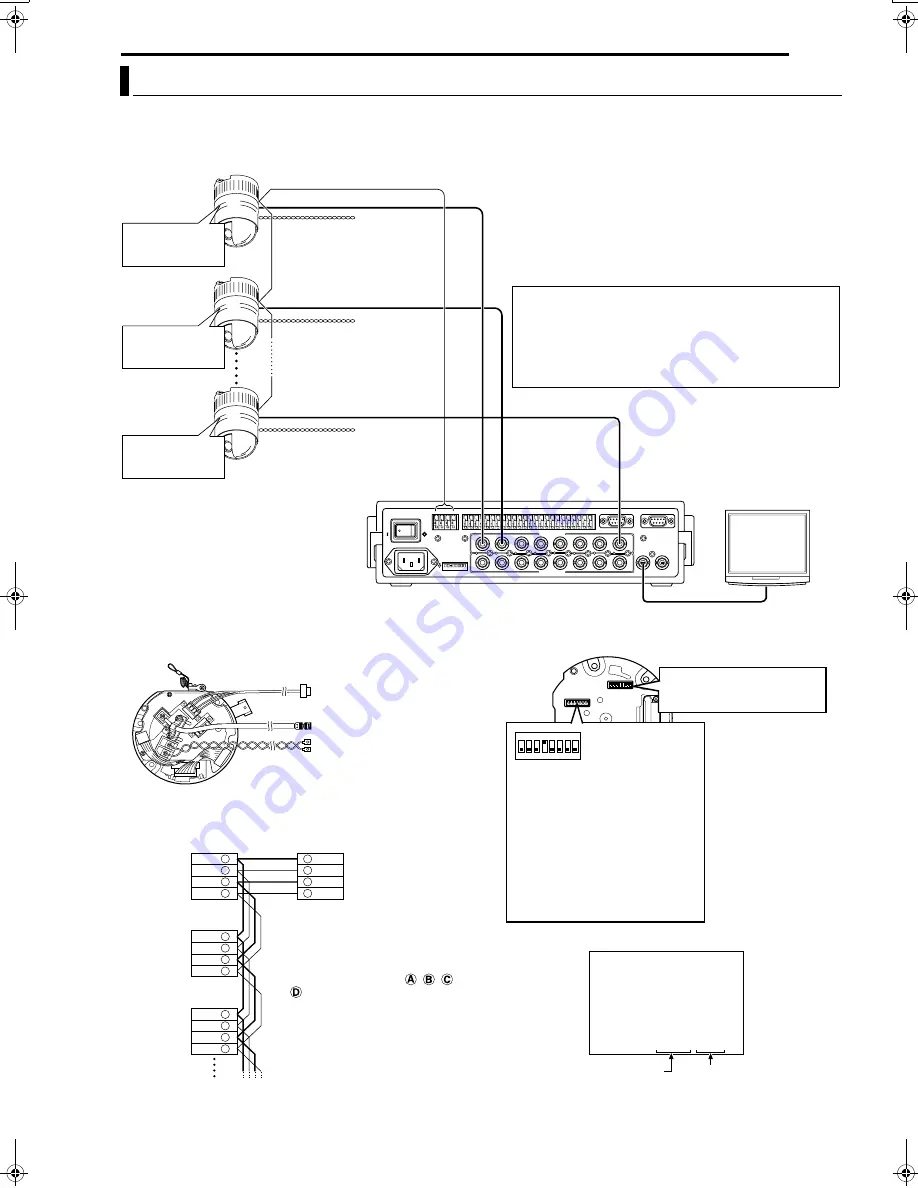
A system that employs the RM-P2580 as the controller.

The following figure shows a system that can accommodate up to eight cameras. (100 positions can be preset per camera.)

8

A

Cable Connections

B

 (

A

pg. 16)

(Terminal side of Ceiling Mount)

8

A

Switch Settings

B

 (

A

pg. 13)

(Setting switches are on the side of the Ceiling Mount)

Multi-Drop Communication System

1

TO CAMERA

DATA I / O

RX+ RX- TX+ TX

TX-

COM

1

2

3

4

5

6

7

8 COM 9/1 10/2 11/3 12/4 13/5 14/6 15/7 16/8 COM

COM

COM

CAMERA

SW

UNIT

ALARM

AUTO

4

3

1 2

8

7

5 6

2

3

4

5

6

7

8

1

MONITOR

OUTPUT

MONITOR

SERIAL-2

SERIAL-1

VIDEO INPUT

VIDEO OUTPUT

OUTPUT

2

1

ON

2

3

4

5

6

7

8

POWER

OFF

ON

AC INPUT

Observe the following points when connecting 
components together:

Turn all the components off before proceeding.

Read the instruction manuals of all components before 
proceeding.

For the types and lengths of connection cables, see 

A

Cable Connections

B

 (

A

pg. 16).

Do not connect the control signal cables in a loop.

CAUTIONS

The AC 24 V power supply must be isolated from the
primary line. (ISOLATED POWER ONLY)

In order to prevent an excessive current flow through
the power supply wire or camera due to a short circuit,
a fuse must be installed in the power supply line.

Camera 1

MACHINE ID: 01
Switch 8: OFF
(RX TERM)

Control signal cable

Remote control unit

RM-P2580

Monitor

Coaxial cable

AC 24 V power 
supply

A

 CAUTIONS

TO CAMERA

MONITOR OUTPUT 1

MACHINE ID: 02
Switch 8: OFF
(RX TERM)

MACHINE ID: 08
Switch 8: ON
(RX TERM)

AC 24 V power 
supply

A

 CAUTIONS

AC 24 V power 
supply

A

 CAUTIONS

TK-C625

Camera 2

TK-C625

Camera 8

TK-C625

TX +
TX -
RX +
RX -

TX +

RX +
RX -
TX +
TX -

TX -
RX +
RX -

TX +
TX -
RX +
RX -

A
B
C
D

A
B
C
D

A
B
C
D

A
B
C
D

Each terminal on the camera and 
the RM-P2580 is marked 

or 

. In order to facilitate 

understanding and to avoid 
connection mistakes, it is 
recommended to connect the 
terminals carrying the same marks.

Control signal cable

Coaxial cable

Power cable

To the TO CAMERA terminal of 
the RM-P2580 and to the next 
camera

To the CAMERA INPUT terminal 
of the RM-P2580

To AC 24V power supply
Listed class 2 input only

Connection of the control signal cable
(A twisted pair cable is recommended.)

Camera 1 
CONTROL 
terminals

Camera 2 
CONTROL 
terminals

Camera 3 
CONTROL 
terminals

RM-P2580 
terminals

<<

>>

: - - I - -

PAN

: - - I - -

TILT

DUPLEX I D- 01

INITIAL PROCESS

PROTOCOL

Set to the Video Input number of 
RM-P2580.
(Setting procedures 

A

pg. 14)

Switch 1 : Invalid (Set to OFF) 
Switch 2 : Invalid (Set to OFF)
Switch 3 : Invalid (Set to OFF)
Switch 4 : ON
Switch 5 : OFF
Switch 7 : Invalid (Set to OFF)
Switch 8 : Set to ON only for the 

camera connected at the 
end of the control signal 
cable. Set to OFF for all 
other cameras.

1

ON

2

3

4

6

7

8

5

Camera 1 monitor display at power ON

Duplex display

A

<Procedures for Checking

Machine ID>

B

 (

A

pg. 14)

ID No. display

Machine ID

TK-C625.book  Page 9  Thursday, March 31, 2005  4:20 PM

Summary of Contents for TK-C625

Page 1: ...254 001A H INSTRUCTIONS TK C625 DOME TYPE CAMERA For Customer Use Enter below the Model No and Serial No which is located on the body Retain this information for future reference Model No TK C625 Serial No ...

Page 2: ...vide reasonable protection against harmful interference in a residential installation This equipment generates uses and can radiate radio frequency energy and if not installed and used in accordance with the instructions may cause harmful interference to radio communications However there is no guarantee that interference will not occur in a particular installation If this equipment does cause har...

Page 3: ...product during a lightning storm or when it is left unattended and unused for long periods of time unplug it form the wall outlet and disconnect the antenna or cable system This will prevent damage to the product due to lightning and power line surges 11 Do not allow anything to rest on the power cord Do not locate this appliance where the cord will be abused by persons walking on it 12 Follow all...

Page 4: ...reset position quickly 8 High image quality Uses a camera with a high resolution of 0 38 mega pixels and a highly sensitive CCD to realize a high image quality of 540 lines Typ and S N50dB Safety Precautions 2 IMPORTANT SAFEGUARDS 3 Introduction 4 Characteristics 4 Contents 4 Operating Precautions 5 Name and Function of Parts 7 Connections Installation 9 Multi Drop Communication System 9 Point to ...

Page 5: ... automatic gain boost by the AGC circuit In this case set AGC to OFF or use the manual iris mode In auto iris mode the iris control button may not function under certain brightness conditions i e when a sufficient amount of light cannot be obtained In this case set the iris mode to manual When the camera is used in ATW Auto White balance mode the colors captured by the camera may differ from the a...

Page 6: ...stained in a very short period in certain operating environments If the dome cover lens becomes excessively contaminated clean it with a lens cleaning cloth or tissue moistened with a solution of neutral detergent in water If this camera is stored in an environment with low temperature with its power turned off a message indicating PLEASE WAIT NOW WARMING UP will appear blinking on the monitor whe...

Page 7: ...tput A pg 17 F Locking Screw For fastening the camera body Ensure to fasten the Camera Clamping Bracket P using this screw G CONTROL Control Signal Terminal J501 Connect this to the remote control unit RM P2580 H Cover This is a protection cover Cut a slit in the rubber cap attached to the cover when wiring cables When connecting cables to the ceiling mount ensure to do so by running the cables th...

Page 8: ...tting Switch For performing settings such as PROTOCOL and SYNC A pg 13 N Auxiliary Switch This switch cannot be used 8 Camera O Camera Connection Terminal Male For connection to the Camera Connection Terminal Female K on the ceiling mount P Camera Clamping Bracket Insert the Locking Screw F into this bracket and tighten to fasten the camera and the ceiling mount Q Lens The lens is not a replaceabl...

Page 9: ...gnal cable Remote control unit RM P2580 Monitor Coaxial cable AC 24 V power supply A CAUTIONS TO CAMERA MONITOR OUTPUT 1 MACHINE ID 02 Switch 8 OFF RX TERM MACHINE ID 08 Switch 8 ON RX TERM AC 24 V power supply A CAUTIONS AC 24 V power supply A CAUTIONS TK C625 Camera 2 TK C625 Camera 8 TK C625 TX TX RX RX TX RX RX TX TX TX RX RX TX TX RX RX A B C D A B C D A B C D A B C D Each terminal on the cam...

Page 10: ... ONLY In order to prevent an excessive current flow through the power supply wire or camera due to a short circuit a fuse must be installed in the power supply line PROTOCOL 1 ON MACHINE ID 01 RX TERM ON PROTOCOL 1 ON MACHINE ID 02 RX TERM OFF PROTOCOL 1 ON MACHINE ID 32 RX TERM OFF CONTROLLER CAM1 CAM2 CAM32 Length of stub CONTROL Cable Length of stub Terminate it with 110 K VIDEO SWITCHER etc An...

Page 11: ...mmunication System Controller Control signal cable Video out Observe the following points when connecting components together Turn all the components off before proceeding Read the instruction manuals of all components before proceeding Switch 4 OFF Point to Point Switch 8 ON Terminated 110 K AC 24 V power supply A CAUTIONS Monitor Control signal cable Coaxial cable Power cable To controller To mo...

Page 12: ...o ON Four wires must be connected Example connection with an RM P2580 Simplex When the camera is controlled using the simplex transmission protocol set the Switch 5 of the Setting switch to ON Two wires must be connected Point to Point Communication System continued RX RX TX TX TX TX RX RX Camera Controller RX RX TX TX TX TX RX RX A B C D A B C D Camera RM P2580 RX RX TX TX Camera Controller ...

Page 13: ...tting OFF LL mode TK C625E 50Hz ONLY TK C625U 60Hz ONLY R RESERVED Switch 7 This switch must be set to OFF R RX TERM Switch 8 This switch sets whether or not the section between control signal terminals RX and RX is to be terminated with a resistance of 110 K Initial setting Terminated 110 K When the system in which this camera is used is a multidrop system RS 485 system set only the camera locate...

Page 14: ...Turn on the power AC 24 V of the camera 3 Camera initializes The following message will appear 4 Check to ensure that DUPLEX and AID LLB are displayed and whether the number coincides with the video input number of RM P2580 If the number is incorrect re set the machine ID MEMO For systems using RM P2580 a set of control signal cables are connected to multiple cameras during use Errors in the switc...

Page 15: ... 4 6 7 8 5 1 ON 2 3 4 6 7 8 5 1 ON 2 3 4 6 7 8 5 1 ON 2 3 4 6 7 8 5 1 ON 2 3 4 6 7 8 5 1 ON 2 3 4 6 7 8 5 1 ON 2 3 4 6 7 8 5 53 54 55 56 57 58 59 60 61 62 63 64 65 66 67 68 69 70 71 72 73 74 75 76 77 78 Machine ID Machine ID Installation Switch 1 ON 2 3 4 6 7 8 5 1 ON 2 3 4 6 7 8 5 1 ON 2 3 4 6 7 8 5 1 ON 2 3 4 6 7 8 5 1 ON 2 3 4 6 7 8 5 1 ON 2 3 4 6 7 8 5 1 ON 2 3 4 6 7 8 5 1 ON 2 3 4 6 7 8 5 1 O...

Page 16: ...er devices C Alarm signal cable A pg 17 For connection to devices with alarm input output terminals D Power cable A pg 18 For connection to an AC 24 V power supply Listed class 2 input only 5 Attach the Cover Attach the Cover to the ceiling mount by following procedure of Step 2 in the reverse order A Attach the cover upon aligning the hole with the Safety Wire Mounting Hole on the ceiling mount f...

Page 17: ...ct this to alarm devices such as an annunciator indicator lamp or buzzer The alarm output terminal is a photocoupler insulated open collector which turns ON during an alarm As these terminals are provided with polarity Ensure that voltage at the terminal is higher than that at the terminal Application of reverse voltage in this case may cause the device to break down Connection of Coaxial Cables C...

Page 18: ...plate is recommended for connection to the AC 24 V terminal to prevent connection errors and disconnection of cables When a 2 conductor VVF vinyl insulated vinyl sheath cable is used the maximum connection lengths are as follows Reference values Cable Connections continued CAUTIONS Mount the Ferrite Core as close as possible the camera within 10 cm Secure the Ferrite Core with the provided Wire Cl...

Page 19: ...diameter of 4 1 mm MEMO Be sure to use 4 screws and attach them firmly The sheet attached to the ceiling mount screw holes of the ceiling mount acts as an insulator between the ceiling mount and the ceiling structure If the ceiling structure is made of a metallic material improper insulation with the camera may cause noise interference in the images To prevent this from occurring ensure proper ins...

Page 20: ...nd turning it in the clockwise direction until it stops Upon doing so check that the Camera Clamping Bracket is aligned with the position of the Locking Screw of the ceiling mount 5 Fasten the Locking Screw Fasten the Locking Screw using a Phillips head screwdriver To dismantle the camera perform procedure from 1 to 5 in the reverse order CAUTION Be sure to connect the Safety Wire Otherwise the ca...

Page 21: ...lting the lever toward the right I increases the value Upon changing the set value of items a change mark will appear as indicated in the left diagram Please refer to the following pages for details on setting of the sub menu 7 Press the MENU button After completing the setup of the menu items press the MENU button to return to the previous menu screen MEMO To prevent malfunction of the camera do ...

Page 22: ...RN SET CHAR SET MENU RETURN SET SUB MENU MENU RETURN MENU RETURN SETUP POSITION SETUP CAMERA CONTROL UNIT CAMERA FUNCTION2 FLIP OFF VAR P T SPEED ON EASY AF OFF AF FOR IR OFF TILT LIMIT M PAN LIMIT OFF AUTO RETURN MENU RETURN POS TITLE EDIT POS 0123456789ABCDEFGHIJKLMNO PQRSTUVWXYZabcdefghijklmno p q r s t u v w x y z ÄÖÜÊÎÔÛÇÑäëïöü âêîôûáéíóúàèìòùçñß CLR CANCEL INS DEL W T Normal screen 1 2 3 4 5...

Page 23: ...UR LEVEL LIGHT TYPE NORMAL MENU RETURN MASK EDIT MENU RETURN SET INVALID DURING PAN MOVEMENT MENU RETURN SET L R L POS SETTING SET INVALID DURING PAN MOVEMENT MENU RETURN SET L R START POS SET MASK DELETE CANCEL DELETE MENU RETURN MENU RETURN DIRECTION STANDARD AXIS SET UP STANDARD AXIS N 1 2 3 4 5 6 MENU RETURN SET CHAR SET CAMERA TITLE EDIT 0123456789ABCDEFGHIJKLMNO PQRSTUVWXYZabcdefghijklmno pq...

Page 24: ...the position where it is facing directly downwards When an object passes beneath the camera the camera will A point downwards B pan 180 and C point upwards In other words the camera needs to perform these 3 steps By using the Auto Flip function helps to reduce the number of operations Set this function when shooting an object that passes beneath the camera OFF Auto Flip is disabled AUTO 1 The came...

Page 25: ...ly be possible within the Tilt Limit that has been set 5 M PAN LIMIT Use this to set the range of Pan horizontal operation during manual operation Setting this will not affect preset positions or Auto Pan Auto Trace and Auto Patrol operations AMANUAL PAN LIMIT SetupB A pg 32 Set values OFF ON OFF AUTO RETURN Camera will be automatically restored to the mode as set in AMODEB if manual operation of ...

Page 26: ...put MEMO Setting the AB W MODEB A pg 27 item to AALARM INB switches the mode to the B W mode and setting cannot be changed OFF POLARITY For setting the polarity of alarm input signals MAKE Input alarm signals when the contact between each alarm input terminal and the GND terminal changes from open to closed BREAK Input alarm signals when the contact between each alarm input terminal and the GND te...

Page 27: ...e AAF FOR IRB A pg 25 item is set to AONB focus can be adjusted automatically during mode switching Make use of an IR light as and when necessary B W MODE For setting the function on switching from Color to B W mode COLOUR Color mode at all times and will not switch to the B W mode For TK C625U this is displayed as ACOLORB B W B W mode at all times AUTO Switches automatically to the Color mode whe...

Page 28: ...ue To brighten the picture Set a larger value Set values 5 to NORMAL to 5 NORMAL AUTO PAN PATROL TRACE Screen Item Function Set Value Initial Value AUTO PAN SET For setting Auto Pan movements AAUTO PAN SetupB A pg 38 AUTO PAN MODE For setting the rotating direction during Auto Pan RETURN Move between the start and end positions RIGHT Rightward rotation LEFT Leftward rotation RETURN AUTO PAN SPEED ...

Page 29: ...nce mode Adjusts the white balance automatically according to the color temperature of the lighting During AATWB setting the AR GAINB and AB GAINB items are displayed as and hue adjustment is not possible AWC Switches to the Auto White Control mode and a message indicating Set Start AWC will be displayed Press the SET button to enable the AWC function for white balance adjustment ATW R GAIN Adjust...

Page 30: ... possible AWC Switches to the Auto White Control mode and a message indicating A SET AWC EXECB will be displayed Press the SET button to enable the AWC function for white balance adjustment ATW R GAIN Adjusts the hue of R red when in the AWC mode Increase value to enhance the red color Set values 0 to 255 B GAIN Adjusts the hue of B blue when in the AWC mode Increase value to enhance the blue colo...

Page 31: ...LETEB and press the SET button The PRIVATE MASK menu reappears after the data has been deleted To cancel deletion select ACANCELB and press the SET button 9 Repeat steps 6 to 8 for each additional mask area 10 Press the MENU button The screen returns to the ACAMERA FUNCTION 1B menu 8 CAUTIONS It is not possible to set five or more masks in adjacent areas Even when this is attempted the masked area...

Page 32: ... positions that have been set and returns the screen to the ACAMERA FUNCTION 2B menu MEMO Tilting zooming and focusing operations are possible when this menu is displayed If a pan limit has already been set the camera will move to the left pan limit position when this menu is invoked Setting cannot be performed when Panning is in progress Press the SET button after Panning has come to a stop Auto ...

Page 33: ...ns are performed without regard to the invalid range as set by the Manual Pan Limit Auto Pan operation Auto Trace operation Movement to preset positions Auto Flip operation 8 Settings that override the Manual Pan Limit The following settings involve Pan operations but setting can be performed without regard to the invalid range as set by the Manual Pan Limit PRIVATE MASK Setup AUTO PAN Setup AREA ...

Page 34: ... to the left Use this to correct previously input characters 7 Repeat steps 5 and 6 for each title character Complete the input of the title for the selected camera in the same way 8 Press the MENU button This stores the camera title that has been set and returns the screen to the previous menu To set the titles for multiple cameras repeat steps 1 to 7 for each camera MEMO Only displayed for the T...

Page 35: ...Press the WIDE button to move the blinking cursor in the Title Input Field leftward Use this when amending the set title 7 Press the FAR button The camera moves to the next area and the AAREA TITLE EDIT AREA 2B screen will be displayed Press the NEAR button to return to the previous area The previous AAREA TITLE EDIT AREA 1B screen will be displayed 8 Repeat Steps 5 to 7 Repeat procedure to enter ...

Page 36: ...n This sets the start position of the direction axis which will be displayed on the top left of the screen Directions are displayed as N north NE north east E east SE south east S south SW south west W west and NW north west respectively MEMO Tilting zooming and focusing operations are possible when this menu is displayed If a start position for the direction axis has already been set the camera w...

Page 37: ...to 7 for each alarm title Complete the input of all the alarm titles AALARM TITLE EDITB 1 to 10 in the same way 9 Press the MENU button The screen returns to the previous menu MEMO Only displayed for the TK C625E model RM P2580 units need to be configured to display alarm titles Use the RM P2580 menu settings to do this A Press and hold the MENU button for 3 seconds to display the SETUP screen on ...

Page 38: ...he RETURN mode This switches the start position to the end position 9 Set the end position only when in the RETURN mode Set the return position using the PAN lever During setting a message indicating AO END POS SETB will be displayed at the bottom right of the screen 10 Press the MENU button The Auto Pan position that has been set will be stored and the screen will return to the previous menu AAUT...

Page 39: ... the patrol positions and time periods of all patrol numbers in the same way 9 Change the Auto Patrol mode Press the FAR button or NEAR button to change the mode After changing to a new mode repeat steps 5 to 8 10 Press the MENU button The screen returns to the previous menu After the above setup Auto Patrol of the camera can be started by pressing the AUTO PATROL button on the RM P2580 To change ...

Page 40: ...ROL TRACEB menu MEMO Saving of auto operations will not be possible when this menu is displayed Manual Pan Limit remains valid when this menu is displayed Manual Pan Limit can be set upon exiting this menu without affecting the Auto Trace operation Auto Trace allows easy recording of manual operations but positions may not be accurately reproduced during playback To Start Auto Trace Function To le...

Page 41: ...tle is now confirmed and the system gets ready for the input of the second character is possible If the WIDE button is pressed the title input field moves to the left Use this to correct previously input characters 8 Repeat steps 5 to 7 for each title character When the next position is selected the previous position tile is stored in the memory Complete the input of all position titles in the sam...

Page 42: ...oard on the Ceiling Mount Connect the cables properly Power can be turned on but it later turns off when the pan tilt mechanism starts operation Is there a problem with the power cable s connecting the camera to the power supply unit If the power cable s are too long or of an inadequate size the correct voltage may not be supplied due to an increase in cable resistance during the pan tilt operatio...

Page 43: ...ible Contour correction Both horizontal and vertical level adjustable 8 Lens Zoom ratio Approx x12 Focal distance 3 8 mm to 45 6 mm Maximum aperture F1 6 WIDE to F2 7 TELE 8 Pan Tilt Mechanism Panning range 360 endless revolution Panning speed 1 5 s to 180 s Tilting range 0 to 90 Horizontal Straight downwards Horizontal Tilting speed 1 s to 120 s 8 General Power supply TK C625E AC 24 V 50 Hz 1 5 A...

Page 44: ...CAMERA 2005 Victor Company of Japan Limited Printed in Thailand LWT0254 001A H is a Registered Trademark owned by Victor Company of Japan Ltd is a Registered Trademark in Japan the U S A the U K and many other countries ...

Reviews: