


1-10 (No.MB127)
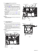
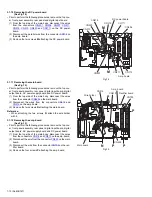
3.1.10 Removing the DC power board
(See Fig.14)
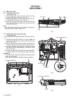
• Prior to perform the following procedures, remove the top cov-
er, front panel assembly, rear panel and digital input board.
(1) From the top side of the main body, disconnect the wires
from the connectors (
CN201
,
CN206
,
CN207
,
CN211
,
CN218
,
CN510
,
CN520
and
CN711
) on the DC power
board.
(2) Disconnect the parallel wire from the connector
CN712
on
the amp. board.
(3) Remove the two screws
M
attaching the DC power board.
Fig.14
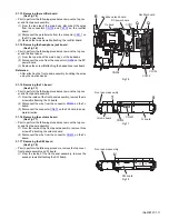
3.1.11 Removing the main board
(See Fig.15)
• Prior to perform the following procedures, remove the top cov-
er, front panel assembly, rear panel, digital input board, digital
output board, AC power supply board and DC power board.
(1) From the top side of the main body, disconnect the wires
from the connector
CN525
on the main board.
(2) Disconnect the wires from the connectors
CN516
and
CN519
on the amp board.
(3) Remove the two screws
N
attaching the main board.
Reference:
• When attaching the two screws
N
, attach the wire holder
with it.
3.1.12 Removing the amp. board
(See Fig.15)
• Prior to perform the following procedures, remove the top cov-
er, front panel assembly, rear panel, digital input board, digital
output board, AC power supply board and DC power board.
(1) From the top side of the main body, disconnect the wires
from the connectors
CN516
and
CN519
on the amp. board.
(2) Disconnect the wire from the connector
CN525
on the main
board.
(3) Disconnect the wire from the connector
CN703
on the rec-
tifier board.
(4) Remove the four screws
P
attaching the amp. board.
Fig.15
CN520
CN510
CN210
CN711
CN712
CN211
CN207
CN206
Amp. board
CN218
M
M
DC power board
P
P
N
P
Main board
CN516
CN519
CN703
CN525
Wire holder
Amp. board
Rectifier board
P


