1-12 (No.22019)
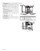
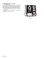
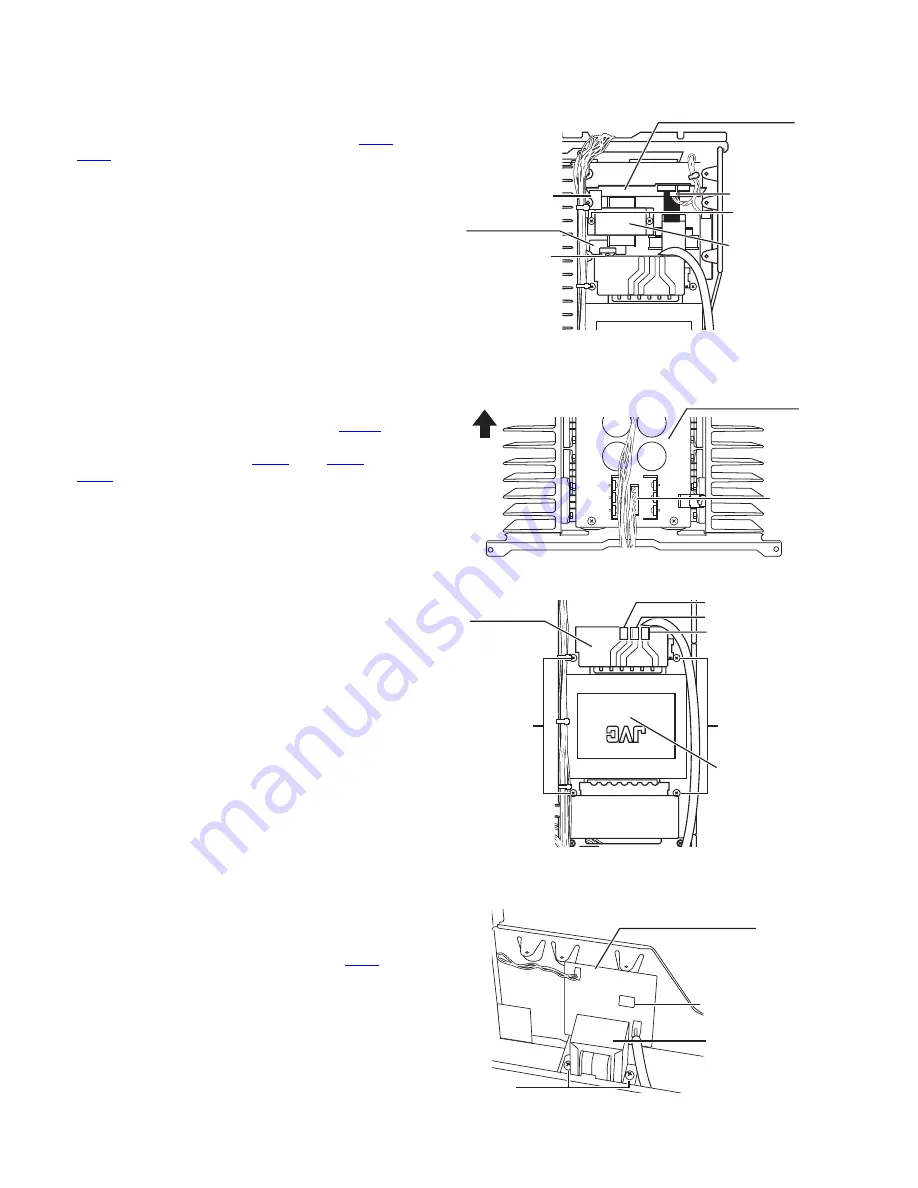
3.1.15 Removing the power transformer 1 with the power supply 2 board
(See Fig.14)
• Prior to performing the following procedure, remove the top
cover and power supply 1 board.
(1) Disconnect the harness from the connector
CN46
and
CN47
on the power supply 2 board.
(2) Remove the two screws
J
attaching the power transformer
1.
3.1.16 Removing the thermal SW 1 board
(See Fig.14)
• Prior to performing the following procedure, remove the top
cover and power supply 1 board.
(1) Remove the screw
K
attaching the thermal SW 1 board.
Fig.14
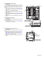
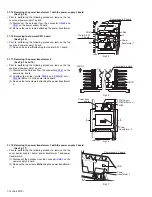
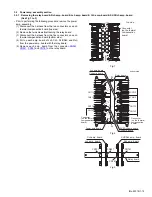
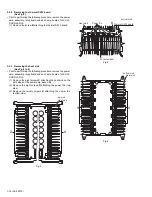
3.1.17 Removing the power transformer 2
(See Fig.15 and 16)
• Prior to performing the following procedure, remove the top
cover and power supply 1 board.
(1) Disconnect the harness from the connector
CN701
on the
power amp. board.
(2) Unsolder the solder points
PW82
and
PW81
(B ver.) /
PW83
(E/EN ver.) on the power trans board.
(3) Remove the four screws
L
attaching the power transformer
2.
Fig.15
Fig.16
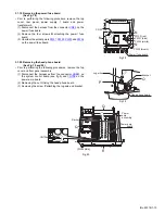
3.1.18 Removing the power transformer 3 with the power supply 3 board
(See Fig.17)
• Prior to performing the following procedure, remove the top
cover, power supply 1 board, power transformer 1 and power
transformer 2.
(1) Disconnect the harness from the connector
CN41
on the
power supply 3 board.
(2) Remove the two screws
M
attaching the power transformer
3.
Fig.17
Thermal SW
1 board
K
Power supply 2 board
CN47
CN46
J
Power
transformer 1
Power amp. board
CN701
FRONT
L
PW83(E/EN ver.)
PW82
Power trans
board
Power
transformer 2
PW81(B ver.)
L
Power supply 3 board
CN41
M
Power
transformer 3

