background image

13

Basic Settings

Speaker distance

Register the unit you use, then the speaker distance from your
listening point.
• If you have set the unit before, start from step 

3

.

• Speaker distance is not valid for the DVD MULTI playback mode.

1

Press SETTING repeatedly until
“UNIT” (with the current setting)*
appears on the display.

* “METER” is the initial setting. If you have already changed the

setting, “FEET” will be shown.

2

Press CONTROL UP 

5

/DOWN 

 to

select the unit.

• Each time you press the button, the setting

alternates between “METER” and “FEET.”

METER

: Speaker distance is shown in meter.

FEET

: Speaker distance is shown in feet.

3

Press SETTING repeatedly until
“FRNT DIS (Front distance),” “CNTR
DIS (Center distance),” or “REAR DIS
(Rear distance)” (with the current setting)*
appears on the display.

• The display shows the current setting in the unit selected in

step 

2

.

* “3.0m” is the initial setting for meter and “10FT” is for feet. If

you have already changed the setting, another value will be
shown.

4

Press CONTROL UP 

5

/DOWN 

to select the appropriate speaker
distance.

• If you have selected “METER” in step 

2

, the

value is changed from “0.3m” to “9.0m” by 0.3 m step.

• If you have selected “FEET” in step 

2

,


the value is changed

from “1FT” to “30FT” by 1 foot step.

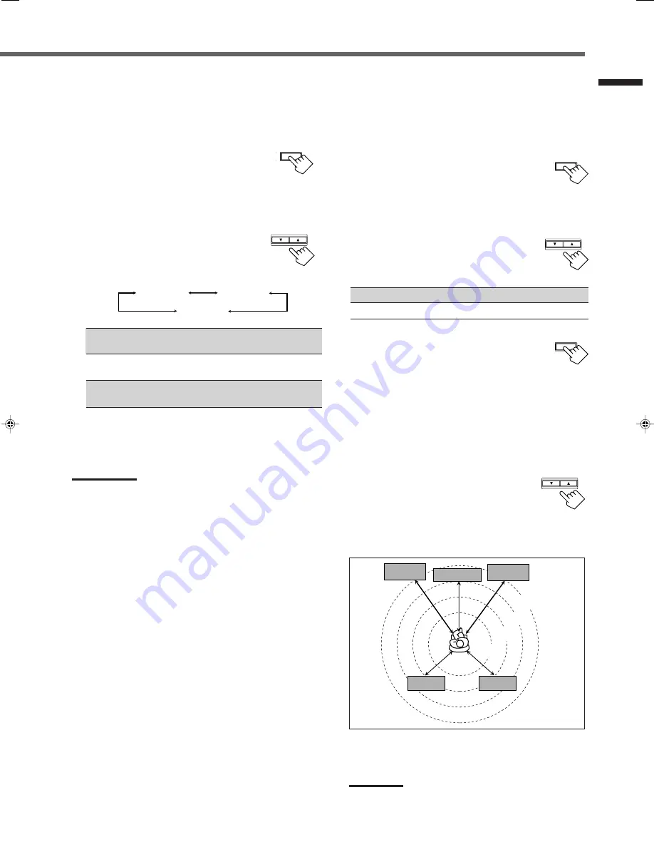
Example: In this case,

set “FRNT DIS” to “3.0m” or “10FT,”
set “CNTR DIS” to “2.7m” or “9FT” and,
set “REAR DIS” to “2.4m” or “8FT.”

Note:

If you have selected “NONE” for the center and rear speakers
setting, you cannot set the speaker distance for the center and rear
speakers.

T SETTING

Speaker size

Register the sizes of all the connected speakers.
• When you change your speakers, register the information about the

speakers again.

1

Press SETTING repeatedly until
“FRNT SP (Front speaker),” “CNTR
SP (Center speaker),” or “REAR SP
(Rear speaker)” (with the current setting)
appears on the display.

2

Press CONTROL UP 

5

/DOWN 

 to

select the appropriate item about the
speaker selected in the above step.

• Each time you press the button, the display

changes as follows:

LARGE

: Select this when the speaker size is relatively large.

(See “Notes” below.)

SMALL

: Select this when the speaker size is relatively small.

(See “Notes” below.)

NONE

: Select this when you have not connected a speaker.

(Not selectable for the front speakers)

3

Repeat step 

1

 and 

2

 to select the appropriate

items for other speakers.

Notes:

• Keep the following comment in mind as reference when adjusting.

– If the size of the cone speaker unit built in your speaker is greater

than 12 cm (4 

3

/

4

 inches), select “LARGE,” and if it is smaller than

12 cm (4 

3

/

4

 inches), select “SMALL.”

• If you have selected “NO” for the subwoofer setting, you can only

select “LARGE” for the front speaker setting.

• If you have selected “SMALL” for the front speaker setting, you

cannot select “LARGE” for the center and rear speaker settings.

SETTING

CONTROL

DOWN

UP

SETTING

CONTROL

DOWN

UP

3.0 m

(10 feet)

Left front

speaker

Right front

speaker

Right rear

speaker

Left rear
speaker

Center speaker

2.7 m

(9 feet)

2.4 m

(8 feet)

2.1 m

(7 feet)

CONTROL

DOWN

UP

LARGE

SMALL

NONE

EN08-17.RX-6020V[J]_f

01.12.7, 4:17 PM

13

Summary of Contents for RX-6020VBK

Page 1: ...J INSTRUCTIONS AUDIO VIDEO CONTROL RECEIVER RX 6020VBK FM MODE PTY PTY SEARCH PTY DVD VCR TV SOUND ADJUST RX 6020V AUDIO VIDEO CONTROL RECEIVER SETTING MASTER VOLUME CONTROL DOWN UP CD TAPE CDR SOURCE NAME INPUT DIGITAL INPUT ANALOG SPEAKERS ON OFF SURROUND MODE PHONES SURROUND ON OFF FM AM TUNING STANDBY FM AM PRESET FM MODE MEMORY INPUT ATT AM D I G I T A L S U R R O U N D STANDBY ON DVD MULTI F...

Page 2: ... FM MODE PTY PTY SEARCH PTY DVD VCR TV SOUND ADJUST RX 6020V AUDIO VIDEO CONTROL RECEIVER SETTING MASTER VOLUME CONTROL DOWN UP CD TAPE CDR SOURCE NAME INPUT DIGITAL INPUT ANALOG SPEAKERS ON OFF SURROUND MODE PHONES SURROUND ON OFF FM AM TUNING STANDBY FM AM PRESET FM MODE MEMORY INPUT ATT AM STANDBY ON DVD MULTI FM INSTRUCTIONS MANUAL D INSTRUCTIONS RECEPTEUR DE CONTROL AUDIO VIDEO AUDIO VIDEO CO...

Page 3: ...ghtning flash with arrowhead symbol within an equilateral triangle is intended to alert the user to the presence of uninsulated dangerous voltage within the product s enclosure that may be of sufficient magnitude to constitute a risk of electric shock to persons The exclamation point within an equilateral triangle is intended to alert the user to the presence of important operating and maintenance...

Page 4: ...ng Off the Power with the Sleep Timer 10 Basic Settings 11 Setting the Digital Input DIGITAL IN Terminals 11 Selecting the Analog or Digital Input Mode 11 Setting the Speaker Information 12 Sound Adjustments 15 Attenuating the Input Signal 15 Adjusting the Front Speakers Output Balance 15 Adjusting the Tone 15 Adjusting the Subwoofer Output Level 15 Tuner Operations 16 Tuning in Stations 16 Using ...

Page 5: ...ULTI FM AM TV SOUND VCR 6 FM MODE button 17 7 DIMMER button 10 8 TV VIDEO button 29 9 VCR CH channel buttons 29 p TV CH channel buttons 29 q STANDBY ON buttons 8 26 29 AUDIO TV VCR DVD w SLEEP button 10 e CD DISC button 28 r ANALOG DIGITAL button 12 t SURROUND ON OFF and SURROUND MODE buttons 20 21 23 28 y MUTING button 10 u TV VOLUME buttons 29 i VOLUME button 9 FM MODE A V CONTROL RECEIVER AUDIO...

Page 6: ...ose the unit to rain or moisture Locations Install the unit in a location that is level and protected from moisture The temperature around the unit must be between 5 C and 35 C 23 F and 95 F Make sure there is good ventilation around the unit Poor ventilation could cause overheating and damage the unit Handling the unit DO NOT touch the power cord with wet hands DO NOT pull the power cord to unplu...

Page 7: ...T REC RIGHT LEFT AM LO OP AM EXIT RIGHT LEFT TAPE CDR IN PLAY OUT REC OUT REC VCR IN PLAY VCR IN PLAY DIGITALIN SUB WOOFER CENTER SPEAKER REAR SPEAKERS RIGHT LEFT FRONT SPEAKERS LEFT CAUTION SPEAKER IMPEDANCE AV COMPULINK RIGHT LEFT REAR MONITOR OUT FR ONT 1 2 3 AM LOOP FM 75 COAXIAL AM EXT ANTENNA FM 75 COAXIAL FM 75 COAXIAL SUBWOOFER OUT AM Loop Antenna supplied or If AM reception is poor connec...

Page 8: ...er Speaker layout diagram NO for the subwoofer LARGE for the front speakers and SMALL for the center and rear speakers are initial settings To get best possible sound change the subwoofer and speaker settings to fit your listening conditions See pages 12 and 13 Right rear speaker DIG ITA L1 DV D DIG ITA L2 CD CD FM 75 COA XIAL AN TEN NA TV SO UN D AUD IO OUT RE C AM LOO P AM EXIT RIG HT LEF T TAP ...

Page 9: ...utput through this receiver may be distorted To audio output CD player Cassette deck or CD recorder To audio output CD recorder To audio output To audio input TAPE CDR CD OUT REC IN PLAY Note You can connect either a cassette deck or a CD recorder to the TAPE CDR jacks When connecting a CD recorder to the TAPE CDR jacks change the source name to CDR which will be shown on the display when selected...

Page 10: ...r to audio mixed output ı To video output Note To enjoy the software encoded with Dolby Digital or DTS Digital Surround you must connect the DVD player using the digital terminal on the rear of this receiver See Digital connections below SUBWOOFER OUT AUDIO CENTER FRONT DVD SUB WOOFER RIGHT LEFT RIGHT REAR LEFT VIDEO VCR OUT REC IN PLAY MONITOR OUT DVD DVD A B Digital connections This receiver is ...

Page 11: ...urce to Play Press one of the source selecting buttons The selected source name appears on the display On the front panel From the remote control DVD MULTI Select the DVD player for viewing the digital video disc using the analog discrete output mode 5 1 ch reproduction To enjoy the DVD MULTI playback see page 24 DVD Select the DVD player VCR Select the VCR TV SOUND Select the TV sound CD Select t...

Page 12: ... decrease the volume turn it counterclockwise From the remote control To increase the volume press VOLUME To decrease the volume press VOLUME CAUTION Always set the volume to the minimum before starting any source If the volume is set at its high level the sudden blast of sound energy can permanently damage your hearing and or ruin your speakers Note The volume level can be adjusted within the ran...

Page 13: ...ically recalled Following can be stored for each source Input attenuator mode see page 15 Balance see page 15 Tone adjustment see page 15 Subwoofer output level see page 15 Surround mode selection see pages 21 23 Notes You cannot assign and store different settings for digital input mode and analog input mode If the source is FM or AM you can assign a different setting for each band For recording ...

Page 14: ...ate digital terminal setting Each time you press the button the display changes as follows 1 DVD 2 CD j 1 DVD 2 TV j 1 DVD 2 CDR j 1 CD 2 DVDj 1 CD 2 TV j 1 CD 2 CDR j 1 TV 2 DVDj 1 TV 2 CD j 1 TV 2 CDR j 1 CDR 2 DVDj 1 CDR 2 CD j 1 CDR 2 TV j back to the beginning Note When shipped from the factory the DIGITAL IN terminals can be used as the digital input for the following components DIGITAL 1 co...

Page 15: ...es between YES and NO YES Select this when you have connected a subwoofer You can adjust the subwoofer output level see page 15 NO Select this when you have not connected or have disconnected a subwoofer From the remote control Press ANALOG DIGITAL The current setting indication appears on the display Each time you press the button the input mode alternates between the analog input ANALOG and the ...

Page 16: ...r speakers setting you cannot set the speaker distance for the center and rear speakers T SETTING Speaker size Register the sizes of all the connected speakers When you change your speakers register the information about the speakers again 1 Press SETTING repeatedly until FRNT SP Front speaker CNTR SP Center speaker or REAR SP Rear speaker with the current setting appears on the display 2 Press CO...

Page 17: ... to the size of the small speaker connected If you have selected LARGE for all speakers this function will not take effect Crossover frequency is not valid for DVD MULTI playback mode and HEADPHONE mode 1 Press SETTING repeatedly until CROSS Crossover with the current setting appears on the display 100HZ is the initial setting If you have already changed the setting another frequency will be shown...

Page 18: ... ON OFF MODE MUTING VCR CH TV CH VOLUME TV SOUND VCR ANALOG DIGITAL REAR R 100 1 4 7 P 10 2 5 8 0 3 6 9 10 REMOTE CONTROL RM SRX6020J REW FF TVVOLUME STANDBY ON INPUT ANALOG INPUT ATT Display INPUT ATT ADJUST CONTROL UP 5 DOWN Remote NOT Remote NOT Remote NOT CONTROL DOWN UP ADJUST CONTROL DOWN UP SOUND CONTROL DOWN UP ADJUST 1 Press ADJUST repeatedly until BASS or TREBLE with the current setting ...

Page 19: ... CH indicator lights up and the channel number position starts flashing on the display for about 5 seconds 3 Press FM AM PRESET 5 up down to select a channel number while the channel number position is flashing L C S WFR LS RS CH S LFE SPK AUTOMUTING TUNED STEREO VOLUME ANALOG R MEMORY L C S WFR LS RS CH S LFE SPK AUTOMUTING TUNED STEREO VOLUME ANALOG R L C S WFR LS RS CH S LFE SPK AUTOMUTING TUNE...

Page 20: ...at they are activated for the tuner not for the CD player and others See page 28 L C S WFR LS RS CH S LFE SPK AUTOMUTING TUNED STEREO VOLUME ANALOG R MEMORY FM AM PRESET FM AM TEST EFFECT MENU ENTER CENTER REAR L SUBWOOFER REAR R 1 4 7 P 10 2 5 8 0 3 6 9 10 100 RETURN L C S WFR LS RS CH S LFE SPK AUTOMUTING TUNED STEREO VOLUME ANALOG R Selecting the FM Reception Mode When an FM stereo broadcast is...

Page 21: ...of this receiver See page 7 Dolby Digital 5 1 ch encoding method so called discrete multichannel digital audio format records and digitally compresses the left front channel right front channel center channel left rear channel right rear channel and LFE channel signals Since each channel is completely independent from the other channel signals to avoid interference you can obtain much better sound...

Page 22: ... Impossible Mode SURROUND DOLBY DTS PLII PLII LIVE DANCE HALL PAVILION ALL CH Signals OFF stereo DIGITAL SURROUND MOVIE MUSIC CLUB CLUB STEREO Dolby Digital 䡬 䡬 Multichannel Dolby Digital 䡬 䡬 䡬 2 channel DTS Digital Surround 䡬 䡬 Multichannel DTS Digital Surround 䡬 䡬 䡬 2 channel Linear PCM 䡬 䡬 䡬 䡬 䡬 䡬 䡬 䡬 Analog 䡬 䡬 䡬 䡬 䡬 䡬 䡬 䡬 All Channel Stereo This mode can reproduce a larger stereo sound field ...

Page 23: ...ATT DIGITAL AUTO LINEAR PCM R SURROUND OFF PL II MOVIE or PL II MUSIC Front speaker When the center speaker is connected 3 channels TV Rear speaker Front speaker Rear speaker When the rear speakers are connected 4 channels TV Center speaker Front speaker Front speaker Rear speaker Rear speaker Front speaker Center speaker Front speaker TV Selecting Surround modes Each time you press SURROUND MODE ...

Page 24: ...button Surround mode turns on and off alternately If you are playing back software encoded with Dolby Digital multichannel DOLBY DIGITAL is selected If you are playing back software encoded with DTS Digital Surround DTS SURROUND is selected If you are playing back any software other than above you can select PL II MUSIC or PL II MOVIE according to the source by pressing SURROUND MODE PRO LOGIC II ...

Page 25: ...E according to the source by pressing SURROUND MODE PRO LOGIC II indicator lights up on the display If you like to adjust sound go to step 3 3 Adjust the speaker output levels 1 Press ADJUST repeatedly until one of the following indications with the current setting appears on the display CENTER To adjust the center speaker output level 10 to 10 REAR L To adjust the left rear speaker output level 1...

Page 26: ...ronger normally set it to EFFECT 3 On the front panel 1 Start playing 2 channel software either analog or Linear PCM and select the source 2 Press SURROUND ON OFF to activate Surround mode When Surround mode turns on the last selected Surround mode will be activated Each time you press the button Surround mode turns on and off alternately 3 Press SURROUND MODE repeatedly until one of the DAP modes...

Page 27: ...analog discrete output mode on a DVD player Once you have made adjustments the receiver memorizes the adjustments until you change them You also need to set the DVD player to the analog discrete output mode Before you start remember There is a time limit in doing the following steps If the setting is canceled before you finish start from step 3 again On the front panel 1 Press DVD MULTI Note When ...

Page 28: ...ts own remote control the receiver automatically turns on and changes the source to the component On the other hand if you select a new source on the receiver or on the remote control the selected component begins playing immediately In both cases the previously selected source continues playing without sound for a few seconds Automatic Power On Off Standby Only possible with the COMPU LINK 3 and ...

Page 29: ...this receiver use the cable with monaural mini plugs You can connect only the TV with AV COMPU LINK EX or AV COMPU LINK III to the AV COMPU LINK terminal Refer also to the manuals supplied with your video components Make sure that the remote control code of the VCR connected to the VCR jacks is set to code A 1 Unplug your VCR DVD player TV and this receiver from the AC outlets 2 Connect your VCR D...

Page 30: ... basic functions listed below Remote Control of the TV DVD player and VCR Using This Remote Control Aim the remote control directly at the remote sensor on each component see page 29 for details One Touch Video Play Simply by inserting a video cassette without its safety tab into the VCR you can enjoy the video playback without setting other switches manually The receiver automatically turns on an...

Page 31: ...t a preset channel number directly For channel number 5 press 5 For channel number 15 press 10 then 5 For channel number 20 press 10 then 10 CD player After pressing CD you can use following buttons for CD operations 3 3 3 3 3 Start playback 4 Return to the beginning of the current or previous track Skip to the beginning of the next track 7 7 7 7 7 Stop playback 8 8 8 8 8 Pause playback To release...

Page 32: ...e that you have changed the source name correctly See page 8 After pressing TAPE CDR you can use following buttons for cassette deck operations 3 3 3 3 3 Start playback FF Fast wind the tape from left to right REW Fast wind the tape from right to left 7 7 7 7 7 Stop playback or recording 8 8 8 8 8 Pause playback To release it press 3 3 3 3 3 REC PAUSE Press this button to enter recording pause Pre...

Page 33: ...nd 29 POSSIBLE CAUSE The power cord is not plugged in Speaker signal cables are not connected The SPEAKERS ON OFF button is not set correctly An incorrect source is selected Muting is activated An incorrect input mode analog or digital is selected Connections are incorrect Speaker signal cables are not connected properly The balance is set to one extreme Incoming signal is too weak The station is ...

Page 34: ...tal harmonic distortion Audio Audio Input Sensitivity Impedance 1 kHz DVD VCR TV SOUND CD TAPE CDR 220 mV 47 k Ω Audio Input DIGITAL IN Coaxial DIGITAL 1 DVD 0 5 V p p 75 Ω Optical DIGITAL 2 CD 21 dBm to 15 dBm 660 nm 30 nm Corresponds to Linear PCM Dolby Digital and DTS Digital Surround with sampling frequency 32 kHz 44 1 kHz 48 kHz Audio Output Level TAPE CDR VCR 220 mV Signal to Noise Ratio 66 ...

Page 35: ... 0 4 at 1 kHz Stereo 0 6 at 1 kHz Stereo Separation at REC OUT 35 dB at 1 kHz Alternate Channel Selectivity 45 dB 400 kHz Frequency Response 30 Hz to 15 kHz 0 5 dB 3 dB AM tuner Tuning Range 530 kHz to 1 710 kHz Usable Sensitivity Loop antenna 400 µV m Signal to Noise Ratio 50 dB 100 mV m General Power Requirements AC 120V 60 Hz Power Consumption 180 W 230 VA at operation 2 W in standby mode Dimen...

Page 36: ...VICTOR COMPANY OF JAPAN LIMITED EN FR 0102NHMMDWJEIN J VC ...

Page 37: ...ghtning flash with arrowhead symbol within an equilateral triangle is intended to alert the user to the presence of uninsulated dangerous voltage within the product s enclosure that may be of sufficient magnitude to constitute a risk of electric shock to persons The exclamation point within an equilateral triangle is intended to alert the user to the presence of important operating and maintenance...

Page 38: ...Turning Off the Power with the Sleep Timer 10 Basic Settings 11 Setting the Digital Input DIGITAL IN Terminals 11 Selecting the Analog or Digital Input Mode 11 Setting the Speaker Information 12 Sound Adjustments 15 Attenuating the Input Signal 15 Adjusting the Front Speakers Output Balance 15 Adjusting the Tone 15 Adjusting the Subwoofer Output Level 15 Tuner Operations 16 Tuning in Stations 16 U...

Page 39: ... VCR 6 FM MODE button 17 7 DIMMER button 10 8 TV VIDEO button 29 9 VCR CH channel buttons 29 p TV CH channel buttons 29 q STANDBY ON buttons 8 26 29 AUDIO TV VCR DVD w SLEEP button 10 e CD DISC button 28 r ANALOG DIGITAL button 12 t SURROUND ON OFF and SURROUND MODE buttons 20 21 23 28 y MUTING button 10 u TV VOLUME buttons 29 i VOLUME button 9 FM MODE A V CONTROL RECEIVER AUDIO TV VCR DVD TEST EF...

Page 40: ...net DO NOT expose the unit to rain or moisture Locations Install the unit in a location that is level and protected from moisture The temperature around the unit must be between 5 C and 35 C 23 F and 95 F Make sure there is good ventilation around the unit Poor ventilation could cause overheating and damage the unit Handling the unit DO NOT touch the power cord with wet hands DO NOT pull the power...

Page 41: ...C RIGHT LEFT AM LO OP AM EXIT RIGHT LEFT TAPE CDR IN PLAY OUT REC OUT REC VCR IN PLAY VCR IN PLAY DIGITALIN SUB WOOFER CENTER SPEAKER REAR SPEAKERS RIGHT LEFT FRONT SPEAKERS LEFT CAUTION SPEAKER IMPEDANCE AV COMPULINK RIGHT LEFT REAR MONITOR OUT FR ONT 1 2 3 AM LOOP FM 75 COAXIAL AM EXT ANTENNA FM 75 COAXIAL FM 75 COAXIAL SUBWOOFER OUT AM Loop Antenna supplied or If AM reception is poor connect ou...

Page 42: ... 3 1 2 Speaker layout diagram NO for the subwoofer LARGE for the front speakers and SMALL for the center and rear speakers are initial settings To get best possible sound change the subwoofer and speaker settings to fit your listening conditions See pages 12 and 13 Right rear speaker DIG ITA L1 DV D DIG ITA L2 CD CD FM 75 COA XIAL AN TEN NA TV SO UN D AUD IO OUT RE C AM LOO P AM EXIT RIG HT LEF T ...

Page 43: ...t through this receiver may be distorted To audio output CD player Cassette deck or CD recorder To audio output CD recorder To audio output To audio input TAPE CDR CD OUT REC IN PLAY Note You can connect either a cassette deck or a CD recorder to the TAPE CDR jacks When connecting a CD recorder to the TAPE CDR jacks change the source name to CDR which will be shown on the display when selected as ...

Page 44: ...ut or to audio mixed output ı To video output Note To enjoy the software encoded with Dolby Digital or DTS Digital Surround you must connect the DVD player using the digital terminal on the rear of this receiver See Digital connections below SUBWOOFER OUT AUDIO CENTER FRONT DVD SUB WOOFER RIGHT LEFT RIGHT REAR LEFT VIDEO VCR OUT REC IN PLAY MONITOR OUT DVD DVD A B Digital connections This receiver...

Page 45: ...AM D I G I T A L S U R R O U N D STANDBY ON L C S WFR LS RS CH S LFE SPK PROLOGIC ΙΙ DSP H PHONE AUTOMUTING TUNED STEREO VOLUME INPUT ATT SLEEP DIGITAL AUTO ANALOG DIGITAL LINEAR PCM R SOURCE NAME L C S WFR LS RS CH S LFE SPK VOLUME ANALOG R Current volume level is shown here Current source name appears STANDBY STANDBY ON DVD DVD MULTI VCR TV SOUND CD TAPE CDR SOURCE NAME FM AM TAPE CDR CD DVD DVD...

Page 46: ...se To decrease the volume turn it counterclockwise From the remote control To increase the volume press VOLUME To decrease the volume press VOLUME CAUTION Always set the volume to the minimum before starting any source If the volume is set at its high level the sudden blast of sound energy can permanently damage your hearing and or ruin your speakers Note The volume level can be adjusted within th...

Page 47: ...lly recalled Following can be stored for each source Input attenuator mode see page 15 Balance see page 15 Tone adjustment see page 15 Subwoofer output level see page 15 Surround mode selection see page 21 23 Notes You cannot assign and store different settings for digital input mode and analog input mode If the source is FM or AM you can assign a different setting for each band For recording You ...

Page 48: ...ime you press the button the display changes as follows 1 DVD 2 CD j 1 DVD 2 TV j 1 DVD 2 CDR j 1 CD 2 DVDj 1 CD 2 TV j 1 CD 2 CDR j 1 TV 2 DVDj 1 TV 2 CD j 1 TV 2 CDR j 1 CDR 2 DVDj 1 CDR 2 CD j 1 CDR 2 TV j back to the beginning Note When shipped from the factory the DIGITAL IN terminals can be used as the digital input for the following components DIGITAL 1 coaxial For DVD player DIGITAL 2 opti...

Page 49: ...etween YES and NO YES Select this when you have connected a subwoofer You can adjust the subwoofer output level see page 15 NO Select this when you have not connected or have disconnected a subwoofer From the remote control Press ANALOG DIGITAL The current setting indication appears on the display Each time you press the button the input mode alternates between the analog input ANALOG and the digi...

Page 50: ... rear speakers setting you cannot set the speaker distance for the center and rear speakers T SETTING Speaker size Register the sizes of all the connected speakers When you change your speakers register the information about the speakers again 1 Press SETTING repeatedly until FRNT SP Front speaker CNTR SP Center speaker or REAR SP Rear speaker with the current setting appears on the display 2 Pres...

Page 51: ...the size of the small speaker connected If you have selected LARGE for all speakers this function will not take effect Crossover frequency is not valid for DVD MULTI playback mode and HEADPHONE mode 1 Press SETTING repeatedly until CROSS Crossover with the current setting appears on the display 100HZ is the initial setting If you have already changed the setting another frequency will be shown 2 P...

Page 52: ...N OFF MODE MUTING VCR CH TV CH VOLUME TV SOUND VCR ANALOG DIGITAL REAR R 100 1 4 7 P 10 2 5 8 0 3 6 9 10 REMOTE CONTROL RM SRX6020J REW FF TVVOLUME STANDBY ON INPUT ANALOG INPUT ATT Display INPUT ATT ADJUST CONTROL UP 5 DOWN DVD DVD MULTI VCR TV SOUND ADJUST RX 6020V AUDIO VIDEO CONTROL RECEIVER SETTING MASTER VOLUME CONTROL DOWN UP CD TAPE CDR SOURCE NAME INPUT DIGITAL INPUT ANALOG SPEAKERS ON OF...

Page 53: ...s up and the channel number position starts flashing on the display for about 5 seconds 3 Press FM AM PRESET 5 up down to select a channel number while the channel number position is flashing L C S WFR LS RS CH S LFE SPK AUTOMUTING TUNED STEREO VOLUME ANALOG R MEMORY L C S WFR LS RS CH S LFE SPK AUTOMUTING TUNED STEREO VOLUME ANALOG R L C S WFR LS RS CH S LFE SPK AUTOMUTING TUNED STEREO VOLUME ANA...

Page 54: ...re that they are activated for the tuner not for the CD player and others See page 28 L C S WFR LS RS CH S LFE SPK AUTOMUTING TUNED STEREO VOLUME ANALOG R MEMORY FM AM PRESET FM AM TEST EFFECT MENU ENTER CENTER REAR L SUBWOOFER REAR R 1 4 7 P 10 2 5 8 0 3 6 9 10 100 RETURN L C S WFR LS RS CH S LFE SPK AUTOMUTING TUNED STEREO VOLUME ANALOG R Selecting the FM Reception Mode When an FM stereo broadca...

Page 55: ...his receiver See page 7 Dolby Digital 5 1 ch encoding method so called discrete multichannel digital audio format records and digitally compresses the left front channel right front channel center channel left rear channel right rear channel and LFE channel signals Since each channel is completely independent from the other channel signals to avoid interference you can obtain much better sound qua...

Page 56: ...l 䡬 Possible Impossible Mode SURROUND DOLBY DTS PLII PLII LIVE DANCE HALL PAVILION ALL CH Signals OFF stereo DIGITAL SURROUND MOVIE MUSIC CLUB CLUB STEREO Dolby Digital 䡬 䡬 Multichannel Dolby Digital 䡬 䡬 䡬 2 channel DTS Digital Surround 䡬 䡬 Multichannel DTS Digital Surround 䡬 䡬 䡬 2 channel Linear PCM 䡬 䡬 䡬 䡬 䡬 䡬 䡬 䡬 Analog 䡬 䡬 䡬 䡬 䡬 䡬 䡬 䡬 All Channel Stereo This mode can reproduce a larger stereo ...

Page 57: ...DIGITAL AUTO LINEAR PCM R SURROUND OFF PL II MOVIE or PL II MUSIC Front speaker When the center speaker is connected 3 channels TV Rear speaker Front speaker Rear speaker When the rear speakers are connected 4 channels TV Center speaker Front speaker Front speaker Rear speaker Rear speaker Front speaker Center speaker Front speaker TV Selecting Surround modes Each time you press SURROUND MODE Surr...

Page 58: ...ton Surround mode turns on and off alternately If you are playing back software encoded with Dolby Digital multichannel DOLBY DIGITAL is selected If you are playing back software encoded with DTS Digital Surround DTS SURROUND is selected If you are playing back any software other than above you can select PL II MUSIC or PL II MOVIE according to the source by pressing SURROUND MODE PRO LOGIC II ind...

Page 59: ...rding to the source by pressing SURROUND MODE PRO LOGIC II indicator lights up on the display If you like to adjust sound go to step 3 3 Adjust the speaker output levels 1 Press ADJUST repeatedly until one of the following indications with the current setting appears on the display CENTER To adjust the center speaker output level 10 to 10 REAR L To adjust the left rear speaker output level 10 to 1...

Page 60: ...e becomes stronger normally set it to EFFECT 3 On the front panel 1 Start playing 2 channel software either analog or Linear PCM and select the source 2 Press SURROUND ON OFF to activate Surround mode When Surround mode turns on the last selected Surround mode will be activated Each time you press the button Surround mode turns on and off alternately 3 Press SURROUND MODE repeatedly until one of t...

Page 61: ...g discrete output mode on a DVD player Once you have made adjustments the receiver memorizes the adjustments until you change them You also need to set the DVD player to the analog discrete output mode Before you start remember There is a time limit in doing the following steps If the setting is canceled before you finish start from step 3 again On the front panel 1 Press DVD MULTI Note When you s...

Page 62: ...automatically turns on and changes the source to the component On the other hand if you select a new source on the receiver or on the remote control the selected component begins playing immediately In both cases the previously selected source continues playing without sound for a few seconds Automatic Power On Off Standby Only possible with the COMPU LINK 3 and COMPU LINK 4 Both the CD player and...

Page 63: ...ayer to this receiver use the cable with monaural mini plugs You can connect only the TV with AV COMPU LINK to the AV COMPU LINK terminal Refer also to the manuals supplied with your video components Make sure that the remote control code of the VCR connected to the VCR jacks is set to code A 1 Unplug your VCR DVD player TV and this receiver from the AC outlets 2 Connect your VCR DVD player TV and...

Page 64: ...ou to use five basic functions listed below Remote Control of the TV DVD player and VCR Using This Remote Control Aim the remote control directly at the remote sensor on each component see page 29 for details One Touch Video Play Simply by inserting a video cassette without its safety tab into the VCR you can enjoy the video playback without setting other switches manually The receiver automatical...

Page 65: ...preset channel number directly For channel number 5 press 5 For channel number 15 press 10 then 5 For channel number 20 press 10 then 10 CD player After pressing CD you can use following buttons for CD operations 3 3 3 3 3 Start playback 4 Return to the beginning of the current or previous track Skip to the beginning of the next track 7 7 7 7 7 Stop playback 8 8 8 8 8 Pause playback To release it ...

Page 66: ...d below make sure that you have changed the source name correctly See page 8 After pressing TAPE CDR you can use following buttons for cassette deck operations 3 3 3 3 3 Start playback FF Fast wind the tape from left to right REW Fast wind the tape from right to left 7 7 7 7 7 Stop playback or recording 8 8 8 8 8 Pause playback To release it press 3 3 3 3 3 REC PAUSE Press this button to enter rec...

Page 67: ...9 POSSIBLE CAUSE The power cord is not plugged in Speaker signal cables are not connected The SPEAKERS ON OFF button is not set correctly An incorrect source is selected Muting is activated An incorrect input mode analog or digital is selected Connections are incorrect Speaker signal cables are not connected properly The balance is set to one extreme Incoming signal is too weak The station is too ...

Page 68: ... than 0 8 total harmonic distortion Audio Audio Input Sensitivity Impedance 1 kHz DVD VCR TV SOUND CD TAPE CDR 220 mV 47 k Ω Audio Input DIGITAL IN Coaxial DIGITAL 1 DVD 0 5 V p p 75 Ω Optical DIGITAL 2 CD 21 dBm to 15 dBm 660 nm 30 nm Corresponds to Linear PCM Dolby Digital and DTS Digital Surround with sampling frequency 32 kHz 44 1 kHz 48 kHz Audio Output Level TAPE CDR VCR 220 mV Signal to Noi...

Page 69: ... at 1 kHz Stereo 0 6 at 1 kHz Stereo Separation at REC OUT 35 dB at 1 kHz Alternate Channel Selectivity 45 dB 400 kHz Frequency Response 30 Hz to 15 kHz 0 5 dB 3 dB AM tuner Tuning Range 530 kHz to 1 710 kHz Usable Sensitivity Loop antenna 400 µV m Signal to Noise Ratio 50 dB 100 mV m General Power Requirements AC 120V 60 Hz Power Consumption 180 W 230 VA at operation 2 W in standby mode Dimension...

Page 70: ...rized servicer or visit our website at www JVC com Remember to retain your Bill of Sale for Warranty Service Do not service the television yourself Caution To prevent electrical shock do not open the cabinet There are no user serviceable parts inside Please refer to qualified service personnel for repairs Accessories To purchase accessories for your JVC product please call toll free 1 800 882 2345...

Page 71: ...cleaning 4 Damage that occurs in shipment due to act of God and cosmetic damage 5 Signal reception problems and failures due to line power surge 6 Video Pick up Tubes CCD Image Sensor Cartridge Stylus Needle are covered for 90 days from the date of purchase 7 Batteries except that Rechargeable Batteries are covered for 90 days from the date of purchase There are no express warranties except as lis...

Page 72: ...VICTOR COMPANY OF JAPAN LIMITED EN 1201NHMMDWJEIN J VC ...

Reviews: