background image

1-15

S1

11

12

13

14

15

S4

S3

21

20

S1

18

19

S2

16

17

S4

S1

S1

9

8

Summary of Contents for RC-ST1BK

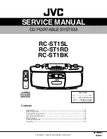
Page 1: ...Y OF JAPAN LTD RC ST1SL RC ST1RD RC ST1BK Contents Area Suffix B U K E Contnental Europe EN Northern Europe EV Eastern Europe Specification 1 2 SafetyPrecautions 1 3 Importantoflaserproducts 1 5 preventingstaticelectricity 1 6 BlockDiagram 1 8 SchematicDiagrams 1 10 Assembly 1 14 ...

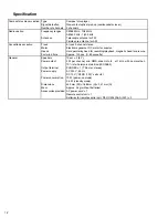
Page 2: ...ermalloy head for recording playback magnetic head for erasure Fast wind time Approx 120 sec C 60 cassette General Speakers 10 cm 2 8 Power output 2 W per channel min RMS driven into 8 at 1 kHz with no more than 10 total harmonic distortion IEC 268 3 Output terminal PHONES 1 3 5 mm stereo Power supply AC 230 V 50 Hz DC 12 V R20 D 13F cells 8 Power consumption 19 W power on mode 2 5 W standby mode ...

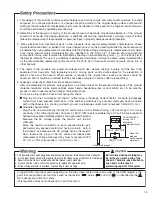
Page 3: ...antenna terminals knobs metal cabinet screw heads headphone jack control shafts etc to be sure the product is safe to operate without danger of electrical shock Do not use a line isolation transformer during this check Plug the AC line cord directly into the AC outlet Using a Leakage Current Tester measure the leakage current from each exposed metal parts of the cabinet particularly any exposed me...

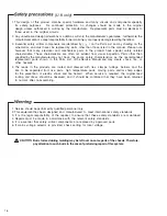
Page 4: ...ge resulting therefrom 3 Essential safety critical components are identified by on the Parts List and by shading on the schematics and must never be replaced by parts other than those listed in the manual Please note however that many electrical and mechanical parts in the product have special safety related characteristics These characteristics are often not evident from visual inspection Parts o...

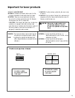
Page 5: ...ad Betrakta ej strålen VARO Avattaessa ja suojalukitus ohitettaessa olet alttiina näkymättömälle lasersäteilylle Älä katso säteeseen ADVARSEL Usynlig laserstråling ved åbning når sikkerhedsafbrydere er ude af funktion Undgå udsættelse for stråling ADVARSEL Usynlig laserstråling ved åpning når sikkerhetsbryteren er avslott unngå utsettelse for stråling Position and position of labels WARNING LABEL ...

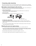
Page 6: ...ort and before installation both sides of the laser diode on the replacement optical pickup are shorted After replacement return the shorted parts to their original condition Refer to the text 2 Do not use a tester to check the condition of the laser diode in the optical pickup The tester s internal power source can easily destroy the laser diode Handling the traverse unit optical pickup 1 Do not ...

Page 7: ...1 7 M E M O ...

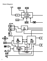
Page 8: ...1 8 Block Diagram ...

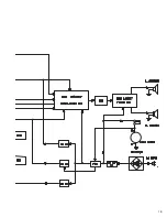
Page 9: ...1 9 ...

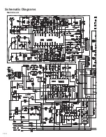
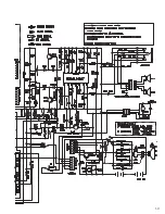
Page 10: ...1 10 Main Circuit Schematic Diagrams ...

Page 11: ...1 11 ...

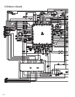
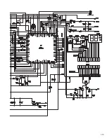
Page 12: ...1 12 CD Servo Circuit ...

Page 13: ...1 13 ...

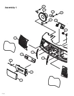
Page 14: ...1 14 Assembly 1 S1 18 19 S1 S1 10 11 7 5 4 6 3 2 1 ...

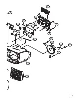
Page 15: ...1 15 S1 11 12 13 14 15 S4 S3 21 20 S1 18 19 S2 16 17 S4 S1 S1 9 8 ...

Page 16: ...1 16 Assembly 2 17 6 7 S10 5 4 3 2 1 8 7 9 S9 11 12 13 S8 10 14 18 19 S6 20 S7 22 21 16 15 S3 S2 S1 23 S4 S5 ...

Page 17: ...1 17 M E M O ...

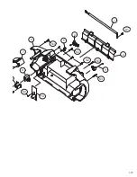
Page 18: ...1 18 Assembly 3 S7 S7 S6 S8 S8 11 S5 9 8 S 7 FRONT CABINET CD TRAY ...

Page 19: ...1 19 8 S4 10 7 6 S3 S3 S3 S3 S2 5 4 1 3 2 S1 ...

Page 20: ... No MB062 2003 11 JVC Euorpe Limited JVC House JVC Budiness Park 12 Priestley Way London NW2 7BA United Kingdom ...

Reviews: