1-10 (No.YA229)
SECTION 3
DISASSEMBLY
3.1
DISASSEMBLY PROCEDURE (DISPLAY UNIT)
NOTE:
• When exchanging parts etc. with the front side (PDP side) fancing down, place a protection sheet under the DISPALY UNIT to
prevent scratches on the front side.
• It is advisable to take notes of the connecting locations (connector numbers) of the removed connectors.
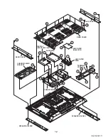
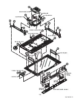
3.1.1 REMOVING THE REAR COVER (Fig.1)
(1) Remove the power cord and the system cable.
(2) Remove the 11 screws
[A]
and the 14 screws
[B]
, then
remove the REAR COVER.
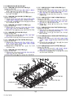
3.1.2 REMOVING THE BACK COVER AND SPEAKER
HOLDER (Fig.1)
(1) Remove the 8 screws
[C]
, then remove the BACK COVER.
(2) Remove the SPEAKER HOLDER.
3.1.3 REMOVING THE CHASSIS SHIELD BRACKET NAD
THE TERMINAL COVER (Fig.1)
• Remove the REAR COVER.
(1) Remove the 6 screws
[D]
, then remove the CHASSIS
SHIELD BRACKET.
(2) Remove the 2 screws
[E]
and the 5 screws
[F]
, then
remove the TERMINAL COVER.
3.1.4 REMOVING THE LINE FILTER PWB (Fig.1)
• Remove the REAR COVER.
• Remove the CHASSIS SHIELD BRACKET.
• Remove the TERMINAL COVER.
(1) Remove the 2 claws
[G]
, then remove the LINE FILTER
INSULATOR.
(2) Disconnect the connector [
CN8001
] from the MAIN
POWER UNIT.
(3) Remove the 2 screws
[H]
and the 1 screw
[I]
, then remove
the LINE FILTER PWB.
3.1.5 REMOVING THE AUDIO PWB (Fig.1.)
• Remove the REAR COVER.
• Remove the CHASSIS SHIELD BRACKET.
• Remove the TERMINAL COVER.
(1) Disconnect the connector [
CN60SL
] / [
CN60CB
] /
[
CN60SR
] from the AUDIO PWB .
(2) Disconnect the connector [
CN9001
] from the SUB POWER
PWB.
(3) Disconnect the connector [
CN00A
] / [
CN00C
] / [
CN00D
]
from the DISPLAY INTERFACE PWB.
(4) Remove the 4 screws
[J]
, then remove the AUDIO PWB.
3.1.6 REMOVING THE DISPLAY INTERFACE PWB (Fig.1)
• Remove the REAR COVER.
• Remove the CHASSIS SHIELD BRACKET.
• Remove the TERMINAL COVER.
(1) Disconnect the connector [
CN00A
] / [
CN00C
] / [
CN00D
] /
[
CN00E
] / [
CN00G
] / [
CN00Q
] / [
CN00T
] / [
CN00X
] /
[
CN00V
] / [
CN0FL
] / [
CN0FR
] / [
CN601
] / [
CNAH1]
from the
DISPLAY INTERFACE PWB .
(2) Remove the 3 screws
[K]
, the 2 screws
[L]
and the 2 screws
[M]
, then remove the DISPLAY INTERFACE PWB.
3.1.7 REMOVING THE CHASSIS BASE (Fig.1)
• Remove the REAR COVER.
• Remove the CHASSIS SHIELD BRACKET.
• Remove the TERMINAL COVER.
• Remove the LINE FILTER PWB.
• Remove the AUDIO PWB.
• Remove the DISPLAY INTERFACE PWB.
(1) Remove the 2 screws
[N]
, then remove the CHASSIS
BASE.
Summary of Contents for PD-Z50DX4
Page 33: ...PDP COLOUR TELEVISION INSTRUCTIONS PD Z50DX4 ENGLISH LCT1781 001A ...
Page 34: ......
Page 90: ...56 ENGLISH ...
Page 91: ......
Page 92: ... 2004 Victor Company of Japan Limited 1104MKH CR VP ...
Page 98: ...1 6 No YA229B PACKING Page 3 34 FRONT FRONT FRONT FRONT 2 7 8 7 7 7 7 7 7 5 2 7 6 8 3 4 1 ...
Page 105: ...2 4 No YA229 ...


