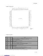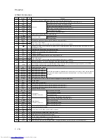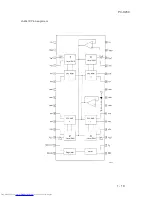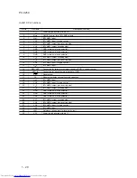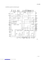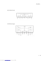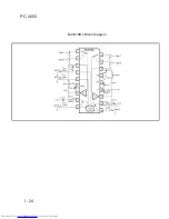
LC72131 Pin Functions
Pin No.
Symbol
(MFP pin Nos. are
Type
Functions
Circuit configuration
in parentheses.)
XIN
XOUT
FMIN
AMIN
CE
CL
DI
DO
V
DD
1 (1)
22 (20)
16 (14)
15 (13)
3 (2)
5 (4)
4 (3)
6 (5)
17 (15)
Xtal OSC
Local oscillator
signal input
Local oscillator
signal input
Chip enable
Clock
Data input
Data output
Power supply
¥ Crystal resonator connection
(4.5/7.2 MHz)
¥ FMIN is selected when the serial data input DVS bit is
set to 1.
¥ The input frequency range is from 10 to 160 MHz.
¥ The input signal passes through the internal divide-by-
two prescaler and is input to the swallow counter.
¥ The divisor can be in the range 272 to 65535. However,
since the signal has passed through the divide-by-two
prescaler, the actual divisor is twice the set value.
¥ AMIN is selected when the serial data input DVS bit is
set to 0.
¥ When the serial data input SNS bit is set to 1:
Ñ The input frequency range is 2 to 40 MHz.
Ñ The signal is directly input to the swallow counter.
Ñ The divisor can be in the range 272 to 65535, and
the divisor used will be the value set.
¥ When the serial data input SNS bit is set to 0:
Ñ The input frequency range is 0.5 to 10 MHz.
Ñ The signal is directly input to a 12-bit programmable
divider.
Ñ The divisor can be in the range 4 to 4095, and the
divisor used will be the value set.
Set this pin high when inputting (DI) or outputting (DO)
serial data.
¥ Used as the synchronization clock when inputting (DI) or
outputting (DO) serial data.
¥ Inputs serial data transferred from the controller to the
LC72131.
¥ Outputs serial data transferred from the LC72131 to the
controller.
The content of the output data is determined by the
serial data DOC0 to DOC2.
¥ The LC72131 power supply pin (V
DD
= 4.5 to 5.5 V)
¥ The power on reset circuit operates when power is first
applied.
PC-X250
1 - 13


