background image

6

INSTALLATION

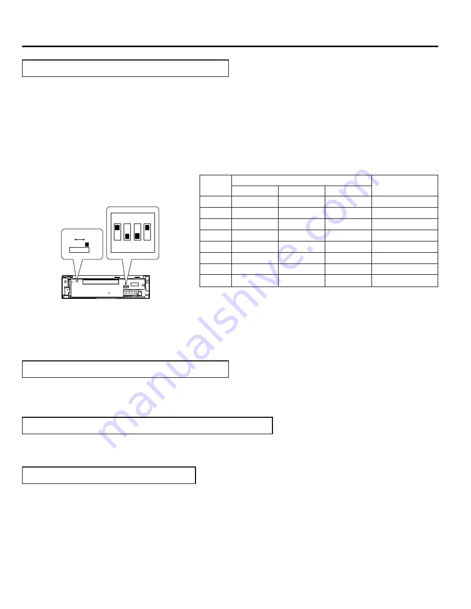
Set the SCSI ID No. between 0 - 7 using only a ID No. that is not being used by other SCSI devices.

Note that the default SCSI ID of the Library is 0 and the SCSI card is 7.

For the details on default factory settings, please refer to the section “SCSI ID No. SETTING” of the instructions
for the JVC Library.

Be sure to set the slide switch to N for use. (The position W is provided for use in servicing.)

9. How to Close and Lock the Door of the JVC Library

Always close and lock the door before switching ON the JVC Library.

1.

Close the door and lock the key cylinder.

8. How to Reattach the Drive Storage Cover

Always reattach the drive storage cover before switching ON the JVC Library.

1.

Fasten the panel with the screws that were removed in procedure ( refer to “2. How to Open the Drive Storage Cover” on
page 4).

10. Automatic Drive Detection Mode

Please also refer to the corresponding sections in the CD/DVD Library instructions.

If using the CD/DVD Library MC-8100U/8200U/8600U, be sure to execute the auto drive detection mode after in-
stalling, adding, exchanging or removing drives, to prevent any malfunction.

1.

While holding the “8” key on the control panel, turn on the power of the Library.

2.

When the LCD display shows “DRIVE DETECTION COMPLETED”, turn off the power of the Library.

3.

Turn the Library on again.

The DRIVE DISPLAY of the CD/DVD Library displays this drive as a “DVD-RAM”.

Before you install, add, remove or replace drives, and/or change the SCSI ID No., turn OFF the power of the host
computer.  Remember to turn it ON again after completing the necessary operations.

7. How to Set the DIP and Slide Switches

Always turn OFF the power of Library when you set the dip switch modes.

(Factory setting)

W

N

ON

OFF

TERM

ID 2

ID 1

ID 0

ON

1

2

3

4

W

N

Default factory setting

SCSI ID 

No.

Switch

Remarks

ID2

OFF

OFF

OFF

OFF

ON

ON

ON

ON

ID1

OFF

OFF

ON

ON

OFF

OFF

ON

ON

ID0

OFF

ON

OFF

ON

OFF

ON

OFF

ON

0

1

2

3

4

5

6

7

2. ID2
3. ID1

This sets the SCSI ID No. on the drives.

4. ID0

1. TERM

This selects the use of the built-in terminator.

Terminate the SCSI bus at the position where it physically terminates.

When using the built-in terminator, set the TERM for the drive located at the physical end of the SCSI bus to ON,
and the TERM for the other drives to OFF.

When not using the built-in terminator, attach an external terminator to the OUT side of the SCSI connector.

When using an external terminator, set TERM of all the drives to OFF.

To improve the stability of SCSI bus communications, it is recommended to use an active external terminator.

Summary of Contents for MC-R421U

Page 1: ... 001A INSTRUCTIONS For Customer Use Enter below the Model No and Serial No which are located at the top of the unit Retain this information for future reference Model No MC R421U Serial No This instruction book is made from 100 recycled paper ...

Page 2: ...tructions carefully in order to obtain the best possible performance 1 DANGER Invisible laser radiation will occur when the unit is open with a failed or defective interlock 2 CAUTION Do not open the top cover There are no user serviceable parts inside the unit leave all servicing to quali fied service personnel ...

Page 3: ... version upgrades and replacement of ROMs please consult the retailer of the MC R421U or JVC service agency Figure shows the MC 8200U Figure shows the MC 8100U Drive locking section Drive locking section Drive locking screw mounting hole Drive locking screw mounting hole 1 How to Open the Door of the JVC Library 䡵 In order to open the door please refer to the section HOW TO OPEN THE DOOR DURING OP...

Page 4: ...e of the MC 8100U in that order without skipping any drive slots 䡵Begin installing drives from the lowest position No 1 1 Insert the DVD R drive from the rear of the JVC Library 䡵 Pay attention not to damage the sensor slit 䡵 Always insert the DVD R Drive correctly 䡵 Check that cables connected on the rear of the unit are not caught or pinched when inserting the DVD R Drive 2 Insert the DVD R Driv...

Page 5: ...used by adding the provided SCSI cable IftheDVD Risrecordedintermittentlyduetoaninsufficiencyintherecordingtransfer rate on the SCSI bus the recording quality may deteriorate and playback malfunc tions may occur 1 While holding the two blind plates remove the four screws on the SCSI connector installa tion section at the rear of the JVC CD DVD Library in order to remove the two blind plates 2 Inse...

Page 6: ...rn on the power of the Library 2 When the LCD display shows DRIVE DETECTION COMPLETED turn off the power of the Library 3 Turn the Library on again 䡵 The DRIVE DISPLAY of the CD DVD Library displays this drive as a DVD RAM 䡵 Before you install add remove or replace drives and or change the SCSI ID No turn OFF the power of the host computer Remember to turn it ON again after completing the necessar...

Page 7: ...nnector 䡵 When interconnecting the JVC CD DVD Library and the host computer with a SCSI cable use a high impedance shield cable with two clamp filters fitted near both connectors 䡵 Signal disturbance may occur if a high impedance shielded SCSI cable is not used Also the above clamp filters are necessary for the JVC CD DVD Library in order to comply with EMI Standard EN55022 Class A Pull the band t...

Page 8: ... each disk drive insertion ejection cycle is counted as one time Accessories SCSI cable with a connector cap 1 m length x 1 Clamp filter with band x 2 ROM x 3 Drive locking screw x 2 Operating environment Temperature 5 C to 35 C Humidity 10 to 80 without condensation Dimensions 171 mm x 47 5 mm x 240 mm WxHxD Weight 1 5 kg Applicable discs DVD R for General 4 7 GB Recommended discs Single sided 4 ...

Page 9: ...OMPANY OF JAPAN LIMITED Printed in Japan LST0033 001A 2001 VICTOR COMPANY OF JAPAN LIMITED is a registered Trademark owned by VICTOR COMPANY OF JAPAN LTD is a registered Trademark in JAPAN the U S A the U K and many other countries ...

Reviews: