background image

COPYRIGHT©  2000 VICTOR COMPANY OF JAPAN, LTD.

EG/EK

Printed in Japan
0400HOV

*

UN

*

VP

VICTOR COMPANY OF JAPAN, LIMITED

EN

G

R

-D
VL
20
0

Summary of Contents for LYT0583-001A

Page 1: ...deo Unit Equipped With A DV Connector 45 Dubbing Images Stored In The Built in Memory To A Tape 46 Dubbing Images Recorded On A Tape To The Built in Memory 47 USING THE REMOTE CONTROL UNIT 48 58 Slow Motion Playback Frame By Frame Playback and Playback Zoom 50 Playback Special Effects 51 Random Assemble Editing 52 For More Accurate Editing 56 Audio Dubbing 58 TROUBLESHOOTING 59 64 USER MAINTENANCE...

Page 2: ...t using the AC Power Adapter Charger for a long period of time it is recommended that you disconnect the power cord from AC outlet Before recording an important scene make sure you only use cassettes with the Mini DV mark remember that this camcorder is not compatible with other digital video formats remember that this camcorder is intended for private consumer use only Any commercial use without ...

Page 3: ...nd manufactured to meet international safety standards but like any electrical equipment care must be taken if you are to obtain the best results and safety is to be assured DO read the operating instructions before you attempt to use the equipment DO ensure that all electrical connections including the mains plug extension leads and interconnections between pieces of equipment are properly made a...

Page 4: ...ucer Picture Navigator PC Connection Cable Audio Video Cable ø3 5 mini plug to RCA plug Editing Cable One plug has 3 rings around the pin and the other has 1 ring around the pin Shoulder Strap Battery Pack BN V408U Lens Cap Already attached to the camcorder Cable Adapter AAA R03 Battery x 2 for remote control unit Core Filter x 1 GR DVL200EG only for optional S Video cable S Video Cable GR DVL200E...

Page 5: ...IGHT to select OFF and press it The normal screen appears 1 R S Z G T I D S R E O O A A D E I E C U O I L M D C T N M N L N O E A U M D Y U M R O U M M L E N D M P B O E R E O E D D A D R E E ME O O N N F U F MENU BRIGHT Wheel GR DVL200EG only GR DVL200EG Owners How To Attach The Core Filter Attach the provided Core Filter to an optional S Video cable The Core Filter reduces interference Release t...

Page 6: ...the adapter during battery charging power is supplied to the camcorder and charging stops Since the AC Power Adapter Charger processes electricity internally it becomes warm during use Be sure to use it only in well ventilated areas When charging the battery pack for the first time or after a long storage period the CHARGE indicator may not light In this case remove the battery pack from the AC Po...

Page 7: ...gaged repeatedly The LCD monitor is used repeatedly The playback mode is engaged repeatedly Before extended use it is recommended that you prepare enough battery packs to cover 3 times the planned shooting time USING AC POWER Use the AC Power Adapter Charger connect as shown in the illustration NOTES The provided AC Power Adapter Charger features automatic voltage selection in the AC range from 11...

Page 8: ...p Attachment 1 Make sure the battery pack or DC cord is removed Following the illustration thread the strap through the eyelet 1 then fold it back and thread it through the buckle 2 Repeat the procedure to attach the other end of the strap to the other eyelet 3 located under the Grip Strap making sure the strap is not twisted CAUTION When using a tripod be sure to open and extend its legs fully to...

Page 9: ...MENU BRIGHT The Menu Screen appears 3 Rotate MENU BRIGHT to select Press it and DISPLAY MENU appears 4 Rotate MENU BRIGHT to select CLOCK ADJ Press it and day is highlighted Rotate MENU BRIGHT to input the day Press it Repeat to input the month year hour and minute Rotate MENU BRIGHT to select 1RETURN and press it twice The Menu Screen closes NOTE Even if you select CLOCK ADJ if the parameter is n...

Page 10: ...over and try again If the cassette holder still does not open turn the camcorder off then on again If the tape does not load properly open the cassette holder cover fully and remove the cassette A few minutes later insert it again When the camcorder is suddenly moved from a cold place to a warm environment wait a short time before opening the cassette holder cover Closing the cassette holder cover...

Page 11: ...it The Sub Menu appears Select SP or LP by rotating MENU BRIGHT and press it Rotate MENU BRIGHT to select 1RETURN and press it twice The Menu Screen closes Audio Dubbing pg 58 is impossible on a tape recorded in the LP mode LP Long Play is more economical providing 1 5 times the recording time NOTES If the recording mode is switched during recording the playback picture will be blurred at the swit...

Page 12: ...ect and press it DSC MENU appears 4 Rotate MENU BRIGHT to select QUALITY and press it The Sub Menu appears Rotate MENU BRIGHT to select the desired mode and press it Rotate MENU BRIGHT to select 1RETURN and press it twice The Menu Screen closes Sub Menu Display MENU BRIGHT Wheel Power Switch Lock Button Menu Screen Power lamp GETTING STARTED cont NOTES The number of storable images depends on the ...

Page 13: ...NO special effects or manual adjustments Suitable for standard recording OFF Allows you to switch off the camcorder Allows you to play back a recording on the tape to display a still image stored in the camcorder s built in memory or to transfer a still image recorded on the tape or in the camcorder s built in memory to a computer VIDEO DSC Switch Position VIDEO Allows you to record on a tape or p...

Page 14: ...itor and set the VIDEO DSC Switch to VIDEO 2 Set the Power Switch to or while pressing down the Lock Button located on the switch Shooting while using the LCD monitor Make sure the LCD monitor is fully open Tilt it upward downward for best viewability Shooting while using the viewfinder Close the LCD monitor The power lamp lights and the camcorder enters the Record Standby mode PAUSE is displayed ...

Page 15: ...maining tape length and the accuracy of the calculation may vary according to the type of tape used TAPE END appears when the tape reaches its end and the power goes off automatically if left in this condition for 5 minutes TAPE END also appears when a cassette at its end is loaded If the Record Standby mode continues for 5 minutes the camcorder s power shuts off automatically To turn the camcorde...

Page 16: ...Snapshot recording will be performed in the FULL mode during Digital Zoom If Snapshot recording is not possible PHOTO blinks when SNAPSHOT is pressed If Programme AE with special effects pg 28 is engaged certain modes of Programme AE with special effects are disabled during Snapshot recording In such a case the icon blinks If SNAPSHOT is pressed when DIS is set to ON pg 24 the Stabiliser will be d...

Page 17: ...hot recording is not possible PHOTO blinks when SNAPSHOT is pressed The Motor Drive mode pg 16 is disabled when the VIDEO DSC Switch is set to If Programme AE with special effects pg 28 is engaged certain modes of Programme AE with special effects are disabled during Snapshot recording In such a case the icon blinks If shooting is not performed for approx 5 minutes when the Power Switch is set to ...

Page 18: ...andby lock the focus by using the manual focus pg 21 then zoom in or out in Record mode Zooming is possible to a maximum of 100X or it can be switched to 10X magnification using the optical zoom pg 23 Zoom magnification of over 10X is done through Digital image processing and is therefore called Digital Zoom During Digital zoom the quality of image may suffer Digital zoom cannot be used when digit...

Page 19: ...nserted during shooting When shooting using a partially recorded tape When shooting on a blank portion located partway through the tape When shooting again after shooting a scene then opening closing the cassette holder cover Recording From The Middle Of A Tape 1 Play back a tape to find the spot at which you want to start recording then engage the Still Playback mode pg 31 2 Set the Power Switch ...

Page 20: ...ON as required OFF Turns off the light AUTO Automatically turns on the light when the camcorder senses insufficient lighting on the subject ON Always keeps the light on as long as the camcorder is turned on The video light can only be used with the camcorder s power on It is recommended to set the white balance pg 30 to when you use the video light When not using the video light turn it off to sav...

Page 21: ...to dry naturally When shooting a subject close to the lens zoom out first pg 18 If zoomed in in the auto focus mode the camcorder may automatically zoom out depending on the distance between the camcorder and the subject This will not occur when TELE MACRO pg 24 is activated FEATURE Manual Focus PURPOSE To obtain correct focus OPERATION 1 If you are using the viewfinder you should already have mad...

Page 22: ...ING Advanced Features For Video And D S C cont Using Menus For Detailed Adjustment This camcorder is equipped with an easy to use on screen menu system that simplifies many of the more detailed camcorder settings pg 23 25 1 Set the Power Switch to while pressing down the Lock Button located on the switch 2 Press MENU BRIGHT The Menu Screen appears 3 Rotate MENU BRIGHT to select the desired functio...

Page 23: ...essing and magnifying images zooming is possible from 10X the optical zoom limit to a maximum of 100X digital magnification Allows you to shoot dark scenes with no picture brightness adjustment The overall appearance may be grainy but the image is bright The shutter speed is automatically adjusted 1 25 1 200 sec Shooting a subject in low or poor lighting at 1 25 sec shutter speed provides a bright...

Page 24: ...tor blinks or goes out if the Stabiliser cannot be used Usually the distance to a subject where the lens is in focus depends on the zoom magnification Unless there is a distance more than 1m to the subject the lens is out of focus at the maximum telephoto setting When set to ON you can shoot a subject as large as possible at a distance of approx 60 cm Depending on the zoom position the lens may go...

Page 25: ...ime and time code from appearing on the connected TV screen Makes the camcorder s display appear on screen when the camcorder is connected to a TV Keeps the indications except the tape running indicator warnings date time time code etc from appearing in the camcorder Also keeps the camcorder s display except the date time and time code from appearing on the con nected TV screen The date time is al...

Page 26: ...f you select Picture Wipe Dissolve during recording press the Recording Start Stop Button when one scene is finished The point at which the scene ended is stored in memory If you select Picture Wipe Dissolve during Record Standby mode press the Recording Start Stop Button to start recording and press it again when one scene is finished The point at which the scene ended is stored in memory If you ...

Page 27: ...reen toward the top and bottom or wipe out from the top and bottom toward the centre leaving a black screen The new scene gradually appears as the old one gradually disappears The new scene wipes in over the previous one from the upper right corner to the lower left corner The next scene gradually wipes in from the centre of the screen toward the corners covering the previous scene The next scene ...

Page 28: ... mode it enhances the classic film effect CLASSIC FILM Gives recorded scenes a strobe effect STROBE Your recording looks like a series of consecutive snapshots VIDEO ECHO Adds a ghost to the subject giving your recording a fantasy feeling Zoom magnification of over 10X is not available SLOW Slow Shutter Lights dark subjects or areas even brighter than they would be under good natural lighting Use ...

Page 29: ...o Pressing the BACKLIGHT button has no effect when the exposure is set to MANUAL and the Power Switch is set to Iris lock indicator Iris Lock Use this function in the following situations When shooting a moving subject When the distance to the subject changes so its size in the LCD monitor or the viewfinder changes such as when the subject is backing away When shooting on a reflective natural back...

Page 30: ...Balance Operation Perform Manual White Balance when shooting under various types of lighting 1 Follow steps 1 through 4 of the white balance adjustment and select MAN 2 Hold a sheet of plain white paper in front of the subject Adjust zoom or position yourself so that the white paper fills the screen 3 Press MENU BRIGHT until begins blinking When the setting is completed stops blinking 4 Press MENU...

Page 31: ...o the AV connector the sound is not heard from the speaker Power Zoom Lever VOL Speaker Lock Button Still Playback Pauses during playback 1 Press 4 6 during playback 2 To resume normal playback press 4 6 again If still playback continues for more than about 3 minutes the camcorder s Stop mode is automatically engaged After 5 minutes in the Stop mode the camcorder s power is automatically turned of...

Page 32: ...o recording mode SP or LP depending on your preference pg 11 ON Enables dubbing of images recorded on a tape to the camcorder s built in memory pg 47 OFF Enables snapshots to be taken during video playback pg 16 Makes the camcorder s indications appear disappear from the connected TV screen Makes the date time appear disappear on the camcorder Makes the time code appear disappear on the camcorder ...

Page 33: ...is called 48 kHz The camcorder cannot detect the sound mode in which the recording was made during fast forward or rewind During playback the sound mode is displayed in the upper left corner SOUND MODE 12BIT MODE Factory preset STEREO SOUND L SOUND R SOUND 1 SOUND 2 MIX Sound is output on both L and R channels in stereo Sound from the L channel is output in stereo Sound from the R channel is outpu...

Page 34: ...ge is displayed 2 Press 3 to display the next image Press 2 to display the previous image NOTE Even if you shoot a new image after playing back a low numbered one this will not overwrite an existing image because new images are automatically stored after the last recorded one PLAYBACK Basic Playback For D S C To display the next image Display To display the previous image Image number Displays the...

Page 35: ...ure Quality mode of the stored image There are 2 modes available FINE and STANDARD pg 12 A star mark is displayed next to still images shot in the FINE mode There are no marks next to still images shot in the STANDARD mode Protect icon When an image is protected against its accidental erasure a padlock mark appears next to the Picture Quality mode indicator and that image cannot be deleted Selecte...

Page 36: ... MENU BRIGHT The Menu Screen appears 3 Rotate MENU BRIGHT to select and press it DSC MENU appears 4 Rotate MENU BRIGHT to select SLIDE SHOW and press it The Slide Show starts 5 To stop the Slide Show press 5 To start the Slide Show without going through the Menu Screen after step 1 press 4 6 To stop the Slide Show press 5 Power Switch Display MENU BRIGHT Wheel PLAYBACK Advanced Features For D S C ...

Page 37: ...CT AN IMAGE Before doing the following perform steps 1 through 3 above 4 Rotate MENU BRIGHT to move the green frame to the desired image and press it A padlock mark appears on the selected image Repeat this procedure for all images you do not wish to delete by accident 5 Rotate MENU BRIGHT upward to select EXIT and press it The normal playback screen appears NOTE When the memory is initialised or ...

Page 38: ... EXECUTE and press it DELETING IN PROGRESS appears The selected images are deleted and the normal playback screen appears To cancel deletion rotate MENU BRIGHT to select CANCEL and press it TO DELETE ALL IMAGES Before doing the following perform steps 1 through 3 above 4 Rotate MENU BRIGHT to select ALL and press it The Deletion Confirmation Screen appears 5 Rotate MENU BRIGHT to select EXECUTE an...

Page 39: ...tate MENU BRIGHT to select and press it DSC MENU appears 4 Rotate MENU BRIGHT to select FORMAT and press it The Sub Menu appears 5 Rotate MENU BRIGHT to select EXECUTE and press it FORMATTING IN PROGRESS appears and the built in memory is initialised When initialisation is finished NO IMAGES STORED appears To cancel initialisation rotate MENU BRIGHT to select CANCEL and press it CAUTION Do not per...

Page 40: ...er Core filter Yellow Not connected S Video cable provided with GR DVL200EK optional for GR DVL200EG TV VCR To IN Set to Y C Cable Adapter provided To TV or VCR B Connection to a TV or VCR equipped with a SCART connector compatible with Y C signal Connector cover To AV To S Core filter Audio Video cable mini plug to RCA plug provided White to AUDIO L IN Red to AUDIO R IN When connecting the cables...

Page 41: ...layback set ON SCREEN to LCD or SIMPLE in the Menu Screen pg 32 Or press DISPLAY on the remote control provided NOTES It is recommended to use the AC Power Adapter Charger as the power supply instead of the battery pack pg 7 When connecting the cables make sure to connect the ends with a core filter to the camcorder The core filter reduces interference To monitor the picture and sound from the cam...

Page 42: ...on the PC NOTES It is recommended to use the AC Power Adapter Charger as the power supply instead of the battery pack pg 7 Never connect the PC connection cable and the DV cable simultaneously to the camcorder Connect only the cable you wish to use to the camcorder The date time information cannot be captured into the PC Refer to the instruction manuals of the provided Software Also refer to the m...

Page 43: ...h to while pressing down the Lock Button located on the switch and turn on the other units NOTES It is recommended to use the AC Power Adapter Charger as the power supply instead of the battery pack pg 7 When using the camcorder for dubbing be sure to use it as a player The camcorder s DV connector is only for output If Still Playback Slow Motion Playback Fast Forward or Rewind is attempted with t...

Page 44: ...Menu Screen pg 32 Time Code set TIME CODE to ON or OFF in the Menu Screen pg 32 Playback Sound Mode Tape Speed And Tape Running Displays set ON SCREEN to LCD or SIMPLE in the Menu Screen pg 32 Or press DISPLAY on the remote control When connecting the cables make sure to connect the ends with a core filter to the camcorder The core filter reduces interference Set the video out select switch of the...

Page 45: ...e the video unit s Record mode 6 Engage the video unit s Record Pause mode and press 4 6 on the camcorder 7 Repeat steps 4 through 6 for additional editing then stop the video unit and camcorder when finished NOTES It is recommended to use the AC Power Adapter Charger as the power supply instead of the battery pack pg 7 If the remote control is used when both the player and recorder are JVC video ...

Page 46: ... on the switch 43 To select a still image to be dubbed perform Index Playback pg 35 or press 2 or 3 to select the image you wish 5 To engage Dub Standby press the Recording Start Stop Button The message TO COPY TO TAPE PUSH START STOP appears 6 While the message is being displayed press the Recording Start Stop Button The selected still image is recorded on the tape for approx 5 seconds The indica...

Page 47: ...ETURN and press it twice The normal playback screen resumes 6 To select a video image to be dubbed start playback by pressing 4 6 At the moment you find the image you wish to dub press it again to engage Still Playback 7 Press MODE to select the Snapshot mode to use for dubbing the image to the built in memory 8 To start dubbing press SNAPSHOT The selected image is stored in the built in memory bl...

Page 48: ... battery compartment cover while pushing up the tab as illustrated 2 Insert two AAA R03 size batteries in the correct direction 3 Re attach the battery compartment cover USING THE REMOTE CONTROL UNIT When using the remote control be sure to point it at the remote sensor The illustration shows the approximate transmitted beam effective area for indoor use The transmitted beam may not be effective o...

Page 49: ...osition or Transmits the beam signal Zoom in out pg 18 Functions the same as the Recording Start Stop Button on the camcorder Functions the same as SNAPSHOT on the camcorder With the camcorder s Power Switch set to Zoom in out pg 50 pg 41 44 53 pg 50 52 pg 50 pg 50 Rewind Reverse Shuttle Search on a tape pg 31 Displays previous image in the built in memory pg 34 pg 54 pg 51 pg 51 pg 53 pg 52 pg 50...

Page 50: ...w Motion Playback During Slow Motion Playback there will be disturbances in video and the picture may seem unstable especially with steady images This is not a malfunction During Slow Motion Playback press PAUSE 6 to pause playback FEATURE Frame By Frame Playback PURPOSE To allow frame by frame search during video playback OPERATION 1 To change from normal to Frame By Frame Playback press PAUSE 6 ...

Page 51: ... 3 Move the highlight bar to the desired effect by pressing EFFECT The selected function is activated and after 2 seconds the menu disappears 䡲 To deactivate the selected effect press EFFECT ON OFF on the remote control Pressing it again re activates the selected effect 䡲 To change the selected effect repeat from step 2 above NOTES When some Playback Special Effects are used the Multi Analyser 4 a...

Page 52: ...urn off the power to the VCR and point the remote towards the VCR s infrared sensor Then referring to the VCR CODE LIST press and hold MBR SET and press button A and then B The code is automatically set once you release MBR SET and the VCR s power comes on 2 Make sure the VCR s power is on Then while holding SHIFT press the button on the remote for the desired function The functions the remote can...

Page 53: ...e Running Displays set ON SCREEN to LCD or SIMPLE in the Menu Screen 墌 pg 32 Or press DISPLAY on the remote control When connecting the cables make sure to connect the end with a core filter to the camcorder The core filter reduces interference Set the video out select switch of the cable adapter as required Y C When connecting to a TV or VCR which accepts Y C signals and uses an S Video cable CVB...

Page 54: ...cial Effects press EFFECT 墌 pg 51 10 Repeat steps 6 through 9 to register additional scenes To change previously registered points press CANCEL on the remote control The registered points disappear one at a time from the most recently registered point If you are not using Fade Wipe or Programme AE with special effects repeat steps 6 and 7 only NOTES When choosing a scene set Edit In and Edit Out p...

Page 55: ...r enters the Pause mode and the VCR enters its Record Pause mode If you do not register an Edit Out point the tape will be dubbed all the way to the end automatically If you operate the camcorder during automatic editing the VCR will enter its Record Pause mode and automatic editing will stop 1 14 Engage the Stop modes for the camcorder and the VCR To make the R A Edit counter display disappear pr...

Page 56: ...MCORDER TIMING 1 Play back the tape in the camcorder then point the remote control at the camcorder s remote sensor and press R A EDIT ON OFF The Random Assemble Editing Menu appears 2 Perform Random Assemble Editing on Programme 1 only In order to check VCR and camcorder timing select the beginning of a scene transition as your Edit In point 3 Play back the dubbed scene If any images from the sce...

Page 57: ...w advance the VCR s record timing by rotating MENU BRIGHT towards You can also delay the VCR s record timing by rotating MENU BRIGHT towards The adjustment range is from 1 3 to 1 3 seconds in 0 1 second increments Press MENU BRIGHT to finish the setting 7 Rotate MENU BRIGHT to select 1RETURN and press it twice Now perform Random Assemble Editing beginning with step 4 on page 54 NOTES Before perfor...

Page 58: ...2BIT MODE to SOUND 2 or MIX in the Menu Screen 墌 pg 32 33 NOTES Sound is not heard from the speaker during Audio Dubbing When editing onto a tape that was recorded at 12 bit the old and new soundtracks are recorded separately If you dub onto a blank space on the tape the sound may be disrupted Make sure you only edit recorded areas If feedback or howling occurs during TV playback move the camcorde...

Page 59: ... dirty or covered with condensation 1 Connect the AC Power Adapter Charger securely 墌 pg 7 Replace the dead battery with a fully charged one 墌 pg 6 7 2 Set the date time 墌 pg 9 Consult your nearest JVC dealer for replacement 3 Set the tape s erase protection tab to REC 墌 pg 10 Set the Power Switch to or 墌 pg 13 Set the VIDEO DSC Switch to VIDEO Replace with new cassette 墌 pg 10 Close the cassette ...

Page 60: ...a or Monotone mode is activated 14 The Sepia Monotone or Slow Shutter mode of Programme AE with special effects is activated WIDE MODE is set to SQUEEZE in the Menu Screen The previously selected mode of Programme AE with special effects was changed after the last selected scene for editing was registered 7 Set it in the right position 墌 pg 10 Install a fully charged battery 墌 pg 6 7 8 Disengage t...

Page 61: ... is set to SQUEEZE in the Menu Screen A Fade In or Fade Out is in progress 19 When shooting in the dark the unit becomes highly sensitive to light and the image takes on an effect similar to Slow Shutter 20 The Picture Wipe or Dissolve function is in use 15 Select Picture Wipe or Dissolve before beginning recording The effects are then automatically activated 墌 pg 26 Do not turn off the camcorder ...

Page 62: ...PLE or TIME CODE is set to OFF in the Menu Screen 27 In places subject to low temperature images become dark due to the characteristics of the LCD monitor When this happens the displayed colours differ from those that are actually recorded This is not a defect of the camcorder When the LCD monitor s fluorescent light reaches the end of its service life images on the LCD monitor become dark Consult...

Page 63: ...dications appear distorted This is not a defect 37 The speaker volume is too great 38 30 Re read the sections covering Fade Wipe effects Programme AE with special effects and DIS 墌 pg 24 26 28 31 32 33 Set the Power Switch to 墌 pg 31 34 Set the VIDEO DSC Switch to Set the Power Switch to 35 Set the TV to the mode or channel appropriate for video playback 墌 pg 40 41 Close the cassette holder cover ...

Page 64: ... attached The LCD monitor s brightness setting is too dark 44 This is not a malfunction 45 The DV cable was plugged unplugged with power turned on 39 Wipe them gently with soft cloth Wiping strongly can cause damage 墌 pg 65 40 Check the section of the manual that explains LCD monitor viewfinder indications 墌 pg 68 72 41 Remove the power supply battery pack etc and wait a few minutes for the indica...

Page 65: ...d clean the interior of the viewfinder with it 2 6 Close the cover Tilt the viewfinder back to the horizontal position NOTES Avoid using strong cleaning agents such as benzine or alcohol Cleaning should be done only after the battery pack has been removed or other power units have been disconnected Mould may form if the lens is left dirty When using a cleaner or chemically treated cloth refer to t...

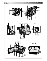
Page 66: ...66EN INDEX Controls Connectors And Indicators P L A Y O FF 1 r p o t u i w q e 3 4 5 6 7 8 Q y Y R U T E 9 0 p 2 ...

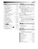
Page 67: ...Level Interface Protocol EDIT 墌 pg 53 Connect the editing cable when performing Random Assemble Editing Connect to a JLIP compatible camcorder or VCR to control it from the computer using the provided Software DC Input Connector 墌 pg 7 The connectors q to e are located beneath a cover q Audio Video Output Connector AV 墌 pg 40 44 53 w Digital Video Connector DV OUT i link 墌 pg 42 43 45 i Link refer...

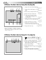
Page 68: ...camcorder 墌 pg 23 9 Displays the Time Code 墌 pg 19 25 Setting ON SCREEN to SIMPLE in the Menu Screen removes indications marked with from the screen 墌 pg 25 32 1 Appears when the VIDEO DSC Switch is set to and the Power Switch is set to or 墌 pg 13 17 2 Appears and blinks during shooting 墌 pg 17 3 Displays the Picture Quality mode of the stored image There are 2 modes available FINE and STD Standar...

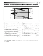
Page 69: ...al effects 墌 pg 28 6 Appears when Digital Image Stabiliser DIS is engaged 墌 pg 24 7 Appears when the focus is adjusted manually 墌 pg 21 Setting ON SCREEN to SIMPLE in the Menu Screen removes indications marked with from the screen 墌 pg 25 32 8 Appears during zooming Zoom level indicator 墌 pg 18 9 Approximate zoom ratio Appears during zooming 墌 pg 18 Appears when GAIN UP is set to AUTO and the shut...

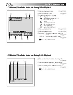
Page 70: ... 4Displays the date time 墌 pg 32 33 5Displays the time code 墌 pg 32 33 6BRIGHT Displays the brightness of the LCD monitor 墌 pg 14 VOLUME Displays the speaker volume 墌 pg 31 The level indicator moves 1 L 2 T B C I T V 1 O 0 S L O U 0 U M 6 N E D 2 1 0 1 L P 1 1 2 4 0 0 0 0 5 2 4 6 1 3 LCD Monitor Viewfinder Indications During D S C Playback 1Displays the index number of the image file 墌 pg 34 2Disp...

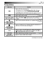
Page 71: ...on the heads Use an optional cleaning cassette 墌 pg 75 Appears if condensation occurs When this indication is displayed wait more than 1 hour until condensation disappears Appears if a tape is not loaded when the Recording Start Stop Button or SNAPSHOT Button is pressed while the Power Switch is set to or and the VIDEO DSC Switch is set to VIDEO Appears when the tape ends during recording or playb...

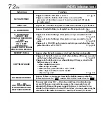
Page 72: ...to the built in memory 墌 pg 47 Appears in the following cases when dubbing still images stored in the built in memory to a tape when condensation occurs when no tape is loaded when the erase protection tab is set to SAVE when a tape in another format is loaded when the tape ends 墌 pg 46 Appears if there are no images stored in the built in memory when the Power Switch is set to and the VIDEO DSC S...

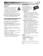
Page 73: ...AUTIONS Battery Packs The supplied battery pack is a lithium ion battery Before using the supplied battery pack or an optional battery pack be sure to read the following cautions 1 To avoid hazards do not burn do not short circuit the terminals When transporting make sure the provided battery cap is attached to the battery If the battery cap is misplaced carry the battery in a plastic bag do not m...

Page 74: ... heat up If you leave power on for a long time the surface around the LCD monitor becomes hot Main Unit 1 For safety DO NOT open the camcorder s chassis disassemble or modify the unit short circuit the terminals of the battery pack Keep it away from metallic objects when not in use allow inflammables water or metallic objects to enter the unit remove the battery pack or disconnect the power supply...

Page 75: ...he printed surface Do not write anything or put a sticker on either the front or back surface If the CD ROM gets dirty gently wipe it with a soft cloth outward from the centre hole using a circular motion Do not use conventional disc cleaners or cleaning spray Do not bend the CD ROM or touch its mirror surface Do not store your CD ROM in a dusty hot or humid environment Keep it away from direct su...

Page 76: ...n VIDEO MENU 墌 pg 32 Monotone 墌 pg 28 A AC Power Adapter Charger 墌 pg 6 7 Audio Dubbing 墌 pg 58 Auto Focus 墌 pg 21 Auto Shut off 墌 pg 15 31 B Backlight Compensation 墌 pg 29 Battery Low 墌 pg 71 Battery Pack 墌 pg 6 7 73 Brighten The LCD Monitor 墌 pg 14 C Channels Left Right 墌 pg 33 Charge The Battery Pack 墌 pg 6 Cinema 墌 pg 24 Classic Film 墌 pg 28 Clean The Camcorder 墌 pg 65 Connections 墌 pg 7 40 42...

Page 77: ...Sepia 墌 pg 28 Set Remote Control VCR Code 墌 pg 52 Shuttle Search 墌 pg 31 Shutter Speed 墌 pg 28 Slide Show 墌 pg 36 Slow Motion Playback 墌 pg 50 Slow Shutter 墌 pg 28 Snapshot 墌 pg 16 17 Snapshot Mode 墌 pg 16 Sound Mode 墌 pg 23 32 33 Speaker Volume 墌 pg 31 Specifications 墌 pg 78 79 Squeeze 墌 pg 24 Still Playback 墌 pg 31 Strobe 墌 pg 28 T Tally 墌 pg 14 23 Tele Macro 墌 pg 24 Time Code 墌 pg 19 25 32 33 T...

Page 78: ... monitor GR DVL200EG 3 0 diagonally measured LCD panel TFT active matrix system GR DVL200EK 2 5 diagonally measured LCD panel TFT active matrix system Viewfinder Electronic viewfinder with 0 24 black white LCD Speaker Monaural For Digital Video Camera Format DV format SD mode Signal format PAL standard Recording Playback format Video Digital component recording Audio PCM digital recording 32 kHz 4...

Page 79: ...l output ø2 5 mm 3 pole JLIP EDIT ø3 5 mm 4 pole AC Power Adapter Charger AA V40EG or AA V40EK Power requirement AC 110 V to 240 V 50 Hz 60 Hz Power consumption 23 W Output Charge DC 7 2 V 1 2 A VTR DC 6 3 V 1 8 A Dimensions W x H x D 68 mm x 38 mm x 110 mm Weight AA V40EG Approx 260 g AA V40EK Approx 340 g Specifications shown are for SP mode unless otherwise indicated E O E Design and specificat...

Page 80: ...COPYRIGHT 2000 VICTOR COMPANY OF JAPAN LTD EG EK Printed in Japan 0400HOV UN VP VICTOR COMPANY OF JAPAN LIMITED EN GR DVL200 ...

Reviews: