6
400mm
400mm
Bracket holes
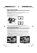
How to attach the stand
NOTE:
• Unplug the AC cord from the AC outlet.
• Ensure that unpacking and transfer of the unit is carried out by two or more people.
• Before beginning this process, assure that TV is laid on a clean, safe, and cushioned space to avoid any
damage to the unit.
• Do not touch or press the TV-screen, glass might break under pressure.
Place the TV on its front onto a table.
Align the stand’s bottom-plate (supplied) as seen here.
It will
fi
t in only one direction.
Hold the unit and attach the stand slowly, as shown in Figure 1.
How to remove the stand
When you transport this product, remove the stand and pack
fl
at against the back of the unit in the carton. To remove the
stand, perform these steps in reverse order.
For wall mounting, the base must be removed. To disconnect the base/stand remove the 4 screws from the back.
Finally secure the bottom-plate with 4 screws (supplied) as indicated by the arrows in Figure 2.
Be sure to follow the instructions. Insufficient tightening or incorrect installation of the stand will not support
your unit correctly, and could result in damage or injury from tip-over.
•
LCD PANEL SIDE
Figure 1
Figure 2
Notes when mounting the LCD TV on a wall
If the unit is to be mounted on the wall, contact the retailer where you purchased the LCD TV for advice, and have the
equipment professionally installed. Incomplete or improper installation may cause injury to you, and/or damage to the LCD
TV.
Bracket holes: To attach a wall mounting bracket (not supplied) remove the screw, then attach where indicated in the
drawing right.
This manufacturer recommends professional installation.
Utilize an appropriate bracket and fasteners, sufficient to accommodate the size and weight of the unit.
Assure the wall to which the unit is to be mounted will safely support the size and weight of the unit, using the bracket and
fasteners you have selected.
Keep cords and cables connected to this flat panel display out of reach of children.
To hang the television on a wall, remove these screws and then remove a stand. Before performing work spread cushioning
over the base area to lay the TV on.
•
•
•
•
•
•
•
Bracket holes
200mm
200mm
Screws
M6 × 10
Illustration is LT-42E910
Illustration is LT-42E910
M8 × 15
Screws
Illustration is LT-46E910
3CQ0221B_En.indd 6
3CQ0221B_En.indd 6
10/6/10 3:52:17 PM
10/6/10 3:52:17 PM
Summary of Contents for LT-42E910
Page 26: ...26 3CQ0221B_En indd 26 3CQ0221B_En indd 26 10 6 10 3 52 43 PM 10 6 10 3 52 43 PM ...
Page 27: ... Memo 3CQ0221B_En indd 27 3CQ0221B_En indd 27 10 6 10 3 52 45 PM 10 6 10 3 52 45 PM ...
Page 53: ... Memo 3CQ0221B_fr indd 27 3CQ0221B_fr indd 27 10 6 10 3 51 47 PM 10 6 10 3 51 47 PM ...
Page 54: ... Memo 3CQ0221B_fr indd 28 3CQ0221B_fr indd 28 10 6 10 3 51 47 PM 10 6 10 3 51 47 PM ...
Page 55: ... Memo 3CQ0221B_fr indd 29 3CQ0221B_fr indd 29 10 6 10 3 51 47 PM 10 6 10 3 51 47 PM ...


