(No.YA303)2-5
2-6(No.YA303)
IC100
208 AVDD_CSS
207
206 ASOY_G-
205 BSOY_G-
204
203 AVSS_CSS
202 TCLK
201 XTAL
200 AVDD_RPLL
199 AVSS_RPLL
198 AVDD_MPLL
197 AVSS_MPLL
196 VDD_MPLL
195 VSS_MPLL
194 AVDD_DDS
193 AVSS_DDS
192 VDD_DDS
191 VSS_DDS
190 ADATA0
189 ADATA1
188 ADATA2
187 ADATA3
186 ADATA4
185 CVDD_9
184 VSS_23
183 ADATA5
182 ADATA6
181 ADATA7
180 ADATA8
179 ADATA9
178 ADATA10
177 ADATA11
176 ADATA12
175 ADATA13
174 ADATA14
173 ADATA15
172 ADATA16
171 ADATA17
170 ADATA18
169 ADATA19
168 ADATA20
167 CVDD_8
166 VSS_22
165 ADATA21
164 ADATA22
163 ADATA23
162 VDD_9
161 VSS_21
160 AHREF_DE
159 ACREF
158 ARAWHS_CS
157 AHS_CS
105
VSS_13
106
VDD6
107
RAMADDR3
108
RAMADDR4
109
RAMADDR5
110
RAMADDR6
111
RAMADDR7
112
RAMADDR8
113
RAMADDR9
114
VSS_14
115
CVDD_5
116
RAMCLK
117
VSS_15
118
RAMADDR2
119
RAMADDR1
120
RAMADDR0
121
RAMADDR10
122
RAMBS1
123
RAMBS0
124
VDD_7
125
RAMC
S
126
RAM_RAS
127
VSS_16
128
RAM_CAS
129
VSS_17
130
CVDD_6
131
RAMWE
132
RAMDQ_MSK
133
RAMDQ8
134
RAMDQ9
135
RAMDQ10
136
RAMDQ11
137
RAMDQ12
138
VSS_18
139
RAMDQ13
140
RAMDQ14
141
VDD_8
142
RAMDQ15
143
RAMDQ7
144
RAMDQ6
145
RAMDQ5
146
VSS_19
147
CVDD_7
148
RAMDQ4
149
RAMDQ3
150
VSS_20
151
RAMDQ2
152
RAMDQ1
153
RAMDQ0
154
ACLK
155
AODD
156
AVS
53
DODD
54
DCLK
55
VDD_3
56
VSS_7
57
DDATA23
58
DDATA22
59
VSS_8
60
DDATA21
61
DDATA20
62
DDATA19
63
DDATA18
64
DDATA17
65
DDATA16
66
DDATA15
67
DDATA14
68
DDATA13
69
DDATA12
70
VDD_4
71
VSS_9
72
DDATA11
73
DDATA10
74
DDATA9
75
DDATA8
76
DDATA7
77
DDATA6
78
DDATA5
79
DDATA4
80
DDATA3
81
DDATA2
82
VSS_10
83
DDATA1
84
DDATA0
85
VSS_11
86
CVDD_4
87
RAMDQ24
88
RAMDQ25
89
VDD_5
90
RAMDQ26
91
RAMDQ27
92
RAMDQ28
93
RAMDQ29
94
RAMDQ30
95
VSS_12
96
RAMDQ31
97
RAMDQ23
98
RAMDQ22
99
RAMDQ21
100
RAMDQ20
101
RAMDQ19
102
RAMDQ18
103
RAMDQ17
104
RAMDQ16
52
DDE_BLANK
51
VDD_2
50
DVS_SYNCT
49
DHS_CS
48
GPIO2
47
GPIO1
46
BDATA0
45
BDATA1
44
BDATA2
43
BDATA3
42
BDATA4
41
CVDD_3
40
VSS_6
39
BDATA5
38
BDATA6
37
BDATA7
36
BDATA8
35
BDATA9
34
BDATA10
33
VSS_5
32
BDATA11
31
BDATA12
30
BDATA13
29
BDATA14
28
BDATA15
27
CVDD_2
26
VSS_4
25
BDATA16
24
BDATA17
23
BDATA18
22
BDATA19
21
VDD_1
20
BDATA20
19
BDATA21
18
BDATA22
17
VSS_3
16
BDATA23
15
BHREF_DE
14
BCREF
13
BRAWHS_CS
12
CVDD_1
11
VSS_2
10
BHS_CS
9
BVS
8
BODD
7
BCLK
6
IRQ
5
RESET
4
SDATA
3
SCS
2
SCL
1
VSS_1
IC101
1
VSS_1
2
PIX_IN
3N
C
4
VDD_1
5
HSYNC
6
RESET
7
SDA
8
SCL
9
VDD_2
10
VSYNC
11
VDD1
12
FBKG
13
B
14
G
15
R
16
VSS_2
SDA_PC
5VSTBY
1N4148
D101
PL101
1
2
3
4
5
6
7
8
9
10
11
12
13
14
15
SDA_PC
100R
R107
5VSTBY
4k7
R109
BZT55C5V1
D109
10k
R106
75R
R103
1N4148
D100
5V_DD
C
50V
22p
C101
50V
22p
C100
5VSTBY
SCL_PC
VGA_B
16V
100n
C102
BZT55C5V1
D108
VSYNC_PCIN
IC102
1
NC1
3
NC3
6
SCL
8
VCC
2
NC2
4
VSS
7
VCLK
5
SDA
75R
R100
75R
R104
75R
R102
100R
R111
10k
R105
100R
R108
VGA_R
4k7
R110
SCL_PC
5V_DDC
VGA_G
75R
R101
HSYNC_PCIN
VCC3_M
MA
0
16V
100n
C107
RAS#
MA
1
CAS#
VCC3_M
VCC
3
CS0#
WE
#
MA
2
50V
10n
C108
WE
#
VCC3
MA
3
CAS#
VCC3
MA
4
VCC3_M
RAS#
50V
10n
C111
16V
100n
C114
MA0
MA
5
BA_0
MA1
MA
6
VCC3_M
VCC3_M
MA2
MA
7
DQ
M
VCC3_M
50V
10n
C109
IC104
1
VDD1
3
VDDQ1
5
DQ2
7
DQ3
9
VDDQ2
11
DQ6
13
DQ7
15
VDD2
17
WE
19
RAS
21
NC2
23
BA
1
25
A0
27
A2
29
VDD3
31
DQ16
33
DQ17
35
VDDQ3
37
DQ20
39
DQ21
41
VDDQ4
43
VDD4
2
DQ0
4
DQ1
6
VSSQ1
8
DQ4
10
DQ5
12
VSSQ2
14
NC1
16
DQM
0
18
CAS
20
CS
22
BA0
24
A10
26
A1
28
DQM
2
30
NC3
32
VSSQ3
34
DQ18
36
DQ19
38
VSSQ4
40
DQ22
42
DQ23
78
VSSQ7
72
VSS3
66
A9
55
VDDQ6
80
DQ1
2
60
A3
81
VDDQ8
75
VDDQ7
56
DQ3
1
59
DQM
3
68
CL
K
52
VSSQ6
82
DQ1
3
85
DQ15
70
NC
6
69
NC
5
84
VSSQ8
54
DQ30
76
DQ9
86
VSS4
79
DQ11
74
DQ8
53
DQ29
67
CK
E
46
VSSQ5
63
A6
51
DQ28
71
DQM
1
57
NC
4
58
VSS2
45
DQ24
62
A5
83
DQ14
48
DQ26
73
NC
7
47
DQ25
65
A8
64
A7
49
VDDQ5
77
DQ10
61
A4
50
DQ27
44
VSS1
MA4
VCC
3
MA
9
16V
100n
C104
DQ
M
MA3
MA10
DQM
VCC3_M
50V
22u
C115
VCC3_M
MA5
DQM
BA_0
16V
100n
C105
16V
100n
C112
MA6
MA7
50V
10n
C110
NKL
16V
100n
C106
NK
L
MA9
VCC3_
M
50V
10n
C113
MA8
CS0#
100R
R123
16V
100n
C124
16V
100n
C127
16V
100n
C137
50V
22u
C138
16V
100n
C126
50V
47n
C117
16V
100n
C128
SW_R
16V
100n
C123
50V
3n9
C133
BLM21A601S
L101
V_DD
16V
100n
C130
V_AD
16V
100n
C121
16V
100n
C122
50V
22u
C139
SW_G
SDA_3.3V
16V
100n
C136
16V
100n
C129
16V
100n
C125
HS_PCOUT
50V
33n
C134
+3.3V
V_AD
V_AD
V_AD
V_DD
V_AD
V_AD
50V
47n
C118
SCL_3.3V
V_D
D
50V
47n
C116
16V
100n
C131
V_AD
3k3
R121
16V
100n
C120
SW_B
V_D
D
50V
1n
C119
50V
1n
C132
VS_PCOUT
IC105
1
GND1
2
GREEN7
3
GREEN6
4
GREEN5
5
GREEN4
6
GREEN3
7
GREEN2
8
GREEN1
9
GREEN0
10
GND2
11
VDD1
12
BLUE7
13
BLUE6
14
BLUE5
15
BLUE4
16
BLUE3
21
GND4
22
VDD2
23
VDD3
24
GND5
25
GND6
26
VD1
27
VD2
28
GND7
29
COAST
30
HSYNC
31
VSYNC
32
GND8
33
FILT
34
PVD1
35
PVD2
36
GND9
45
VD5
46
VD6
47
GND13
48
GAIN
49
SOGIN
50
GND14
51
VD7
52
VD8
53
GND15
54
RAIN
55
AO
56
SCL
57
SDA
58
REFBYPASS
59
VD9
60
GND16
65
SOGOUT
66
HSOUT
67
DATACK
68
GND19
69
VDD4
70
RED7
71
RED6
72
RED5
73
RED4
74
RED3
75
RED2
76
RED1
77
RED0
78
VDD5
79
VDD6
80
GND20
17
BLUE2
18
BLUE1
19
BLUE0
20
GND3
37
MIDSCV
38
CLAMP
39
VD3
40
GND10
41
GND11
42
VD4
43
BAIN
44
GND12
61
GND17
62
VD10
63
GND18
64
VSOUT
100R
R122
GA0
GA3
GA2
GA1
GA7
GA6
GA5
GA4
PANEL_VCC
FDC642P
Q101
1
2
3
4
5
6
BC848B
Q100
10k
R128
+5V_PANEL
PANEL_CONT
10k
R127
+3.3V
S103
S102
BA_1
BA_1
DQM
MA
8
MA10
R1
R2
R3
R4
47R
R130
2
3
4
7
6
5
R1
R2
R3
R4
47R
R131
2
3
4
7
6
5
R1
R2
R3
R4
47R
R132
2
3
4
7
1
8
1
8
1
8
1
8
1
8
1
8
6
5
R1
R2
R3
R4
47R
R133
2
3
4
7
6
5
R1
R2
R3
R4
47R
R134
2
3
4
7
6
5
R1
R2
R3
R4
47R
R135
2
3
4
7
6
5
BA7
BA0
BA5
BA6
BA1
BA3
BA2
BA4
RA3
RA4
RA2
RA1
RA7
RA6
RA5
RA0
PHDE
SCLK
10k
R140
V_DD
S107
HS_PCOUT
VS_PCOUT
CLK_PCOUT
+5V
10k
R141
S109
6015_HSOUT
6015_HSOUT
S111
S112
63V
470n
C146
SOG_PCOUT
S114
SOG_PCOUT
S115
6015_HSOUT
VCLK_MAIN
100R
R145
100R
R146
SDA_5V
SCL_5V
SDA_3.3V
SCL_3.3V
100R
R147
100R
R148
+5V
+5V
16V
100n
C147
OVVS
OVHS
RESET_GM6015
RESET_GM6015
IRQ
OVCLK
OVACTIV
10k
R149
1k
R150
1k
R151
180R
R152
OVACTIV
OVCLK
OVVS
OVHS
14.31818MHz
X100
50V
4p7
C148
50V
4p7
C149
AVDD_3.3
AVDD_3.3
AVDD_3.3
AVDD_3.3
AVDD_3.3
AVDD_3.3
16V
100n
C150
16V
100n
C151
16V
100n
C152
50V
220p
C153
50V
220p
C154
AVDD_3.3
50V
220p
C155
BLM21A601S
L104
CVDD_2.5
50V
22u
C156
16V
100n
C157
CVDD_2.5
50V
220p
C158
CVDD_2.5
50V
220p
C160
CVDD_2.5
50V
220p
C161
CVDD_2.5
50V
22u
C162
16V
100n
C163
CVDD_2.5
50V
220p
C164
CVDD_2.5
16V
100n
C165
CVDD_2.5
50V
220p
C166
CVDD_2.5
16V
100n
C167
+3.3V
+3.3V
16V
100n
C168
50V
220p
C169
+3.3 V
50V
220p
C170
+3.3V
16V
100n
C171
+3.3V
50V
220p
C172
+3.3V
16V
100n
C174
+3.3V
50V
220p
C175
+3.3V
16V
100n
C176
VSYNC_PCIN
10k
R153
+3.3V
50V
22u
C177
16V
100n
C178
AVDD_3.3
R1
R2
R3
R4
47R
R156
2
3
4
7
1
8
6
5
R1
R2
R3
R4
47R
R157
2
3
4
7
6
5
R1
R2
R3
R4
47R
R158
2
3
4
7
6
5
R1
R2
R3
R4
47R
R159
2
3
4
7
6
5
R1
R2
R3
R4
47R
R160
1
2
3
4
7
8
1
8
1
8
1
8
6
5
R1
R2
R3
R4
47R
R161
2
3
4
7
1
8
6
5
BLM21A601S
L105
+3.3V
BLM21A601S
L109
+3.3V
BLM21A601S
L110
+3.3V
PC_R
7
PC_R
6
PC_R
5
PC_R4
PC_R2
PC_R3
PC_R
0
PC_R
1
PC_G7
PC_G1
PC_G2
PC_G4
PC_G0
PC_G5
PC_G6
PC_G3
PC_B6
PC_B0
PC_B3
PC_B7
PC_B5
PC_B2
PC_B4
PC_B1
PC_G 6
PC_G 7
PC_G 5
PC_G 4
PC_G 0
PC_G 3
PC_G 2
PC_G 1
PC_R7
PC_R1
PC_R2
PC_R4
PC_R0
PC_R5
PC_R6
PC_R3
PC_B7
PC_B5
PC_B1
PC_B2
PC_B4
PC_B3
PC_B6
PC_B0
100k
R162
R1
R2
R3
R4
33R
R165
2
3
4
7
18
18
6
5
R1
R2
R3
R4
33R
R166
2
3
4
7
6
5
16V
100u
C185
16V
100n
C183
+5V
IC106
4
VOUT
2 OUT
1
GN D
3
IN
47R
R167
MA1
MA3
+3.3V
MA10
10k
R170
10k
R173
10k
R171
10k
R175
BA_0
+3.3V
DQM
10k
R176
MA8
10k
R180
10k
R168
10k
R177
MA2
10k
R169
10k
R182
MA5
10k
R174
10k
R179
BA_1
+3.3V
MA4
MA6
10k
R172
MA7
MA9
MA0
10k
R181
10k
R178
50V
47p
C186
1k
R183
1k
R184
S117
S118
S119
YUV7
YUV6
YUV5
YUV4
YUV3
YUV2
YUV1
YUV0
CVDD_2.5
16V
100n
C159
PVSYNC
PHSYNC
S104
+12V
5VSTBY
S121
S122
S+3.3V
S123
S124
S+3.3V
S125
S126
10k
R185
50V
47p
C187
S127
+3.3V
VCLK_MAIN
16V
100n
C188
16V
100n
C189
S128
VGA_G
VGA_SW
16V
100n
C190
SW_R
IC107
1
A
3
C
5
E
7
G
10
J
12
L
14
N
16
R
2
B
4
D
6
F
8
H
15
O
13
M
9
I
11
K
HDTV_CB
75R
R191
1k
R189
SW_G
S129
HDTV_CR
HDTV_Y
VGA_R
VGA_B
75R
R192
SW_B
+5V
75R
R190
S130
BC848B
Q102
10k
R193
15k
R194
100k
R195
75R
R196
16V
10u
C191
50V
470p
C192
AVDD_3.3
+5V
SW_G
S131
BAV99
D107
BAV99
D105
+5V
BAV99
D103
S132
S133
S134
INTENSITY
BC848B
Q105
1k5
R136
INTENSITY
BC848B
Q104
1k5
R137
INTENSITY
BC848B
Q103
1k5
R138
INTENSITY
1k
R139
1k
R142
1k
R143
1k
R144
1k
R154
1k
R155
S135
S136
S137
+3.3V
CVDD_2.5
BAV99
D110
BAV99
D111
BAV99
D112
BAV99
D113
5VSTBY
50V
1n
C217
HDTV_Y
50V
15p
C218
BLM21A601S
L111
16V
10u
C219
330R
R197
IC108
1
CSYNC
2
CVBS_IN
3
VSYNC
4
GND
5
BBPO
6
RSET
7
HSYNC
8
VDD
IC109
1Y
0
2Y
2
3
COM_Y_OUT_IN
4Y
3
5Y
1
6
INH
7
VEE
8
GND
9
B
10
A
11
X3
12
X0
13
COM_X_OUT_IN
14
X1
15
X2
16
VCC
BLM21A601R
L112
16V
100n
C220
+5V
50V
10n
C221
HDTV_Y
16V
100n
C222
HDTV_HS
HDTV_VS
16V
100n
C223
S+3.3V
HSYNC_PCIN
HDTV_HS
VSYNC_PCIN
HDTV_VS
VGA_SW
HD_PC_VS
HD_PC_HS
S138
S139
HD_PC_HS
HD_PC_VS
BZT55C5V1
D114
A 1
K 2
5VSTBY
10k
R198
HD_FLAG
S140
S141
S142
16V
100n
C224
VGA_G
16V
100n
C225
HDTV_C S
HDTV_CS
50V
1n
C226
S143
VIN
BLM21A601S
L113
CLK_PCOUT
MD2
7
MD1
6
MD2
8
MD1
7
MD2
9
MD18
MD30
MD
0
MD19
MD31
MD2
0
MD
8
MD2
1
MD9
MD2
2
MD1
0
MD2
3
MD1
1
MD1
2
MD1
3
MD1
4
MD1
5
MD0
MD1
MD1
MD2
MD2
MD3
MD4
MD5
MD7
MD6
MD2
4
MD2
5
MD2
6
MD16
MD17
MD18
MD19
MD20
MD21
MD22
MD23
MD31
MD30
MD24
MD25
MD26
MD27
MD28
MD29
MD
7
MD6
MD
5
MD
4
MD
3
MD15
MD14
MD13
MD12
MD11
MD10
MD
9
MD
8
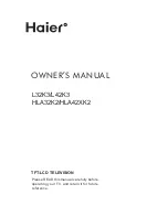
VGA-HDTV SW
MAIN PWB ASS'Y
(1/8)
VE-20191734
CIRCUIT DIAGRAMS
MAIN PWB CIRCUIT DIAGRAM (1/8)