background image

1-16 (No.YA306)

SECTION 4

ADJUSTMENT

This service manual does not describe ADJUSTMENT.

SECTION 5

TROUBLESHOOTING

This service manual does not describe TROUBLESHOOTING.

Summary of Contents for LT-15B60SJ

Page 1: ...r Company of Japan Limited No YA306 2005 10 WIDE LCD PANEL TELEVISION YA306 2005 10 LT 15B60SJ LT 15B60SW TABLE OF CONTENTS 1 PRECAUTION 1 3 2 SPECIFIC SERVICE INSTRUCTIONS 1 7 3 DISASSEMBLY 1 12 4 ADJUSTMENT 1 16 5 TROUBLESHOOTING 1 16 ...

Page 2: ... system TOP German system LCD panel 15V inch 4 3 Screen Size Diagonal 38 1cm H 30 4cm V 22 8cm Display Pixels Horizontal 1024 dots Vertical 768 dots XGA Audio Power Output 3W 3W 10 THD Speaker 3 3cm 10 5cm 2 Aerial terminal VHF UHF F type connector 75Ω unbalanced coaxial EXT 1 Input Output 21 pin Euro connector SCART socket 1 EXT 2 Input S Video Video Audio Mini DIN 4 pin 1 Y 1V p p Positive Negat...

Page 3: ...omponents that indicate evidence of overheating should be replaced Always use the manufacturer s replacement components 6 Isolation Check Safety for Electrical Shock Hazard After re assembling the product always perform an isolation check on the exposed metal parts of the cabinet antenna terminals video audio input and output terminals Control knobs metal cabinet screw heads earphone jack control ...

Page 4: ...aracteristics are identified in the Parts List of Service Manual Electrical components having such features are identified by shading on the schematics and by on the Parts List in the Service Manual The use of a substitute replacement which does not have the same safety characteristics as the recommended replacement part shown in the Parts List of Service Manual may cause shock fire or other hazar...

Page 5: ...g walls as well as the floor etc Install the unit on stable flooring or stands Take precautionary measures to prevent the unit from tipping in order to protect against accidents and earthquakes 1 3 3 NOTES ON HANDLING 1 WHEN TAKING UNIT OUT OF A PACKING CASE When taking the unit out of a packing case do not grasp the upper part of the unit If you take the unit out while grasping the upper part the...

Page 6: ...ring transportation and storage as the LCD panel is very vulnerable to lateral impacts and may break During transportation ensure that the unit is loaded along the traveling direction of the vehicle and avoid stacking them on one another For storage ensure that they are stacked in 2 layers or less even when placed upright 1 4 2 OPTICAL FILTER ON THE FRONT OF THE LCD PANEL 1 Avoid placing the unit ...

Page 7: ...UDIO R input 500mV rms Nominal High impedance Used R1 3 AUDIO L output 500mV rms Nominal Low impedance Used TV OUT 4 AUDIO GND Used 5 GND B Used 6 AUDIO L input 500mV rms Nominal High impedance Used L1 7 B input 700mV B W 75Ω Used 8 FUNCTION SW SLOW SW Low 0V 3V High 8V 12V High impedance Used 9 GND G Used 10 SCL T V LINK Not used 11 G input 700mV B W 75Ω Used 12 SDA Not used 13 GND R Used 14 GND ...

Page 8: ...IGHT FAULT In this pixel fault a cell that should not light originally is lighting on and off For checking this pixel fault input ALL BLACK SCREEN and find out the cell that is lighting on and off DARK FAULT In this pixel fault a cell that should light originally is not lighting or lighting with the brightness twice as brighter as originally lighting For checking this pixel fault input 100 of each...

Page 9: ...nd turns the tv to Stdby 0 002 ISP Mode Sets the TV into ISP state 0 003 DCXO DCXO crystal alignment 70 004 DCXO Auto Automatic DCXO frequency alignment When it is set to 1 UOC automaticaly calculates DCXO values and writes it to item number 3 0 005 Rotation 31 006 Hor Shift 32 007 HBL 0 008 WBF 4 009 WBR 8 010 WSS WSS Wide Screen Sigan ling enable 1 011 Gld SCART 1 012 Col Fe Color Saturation adj...

Page 10: ... 18 072 BGSCAL DEC 0 073 BGSCAL MONO 0 074 BGSCAL NIC 0 075 BGSCAL SAP 0 076 MSCAL DEC 0 077 MSCAL MONO 0 078 MSCAL NIC 0 079 MSCAL SAP 0 080 LSCAL DEC 0 081 LSCAL MONO 0 Item No Setting items Function Setting value 082 LSCAL NIC 0 083 LSCAL SAP 0 084 E2D 0 085 FFI 0 086 CMUTE 1 087 PA BA VO 31 088 PA TR VO 15 089 PA LM VO 1 090 PA ST VO 5 091 PA LO VO 0 092 PA B1 VO 21 093 PA B2 VO 50 094 PA B3 V...

Page 11: ...TIM SW 1 140 TIM OFF 1 141 TIM SKP 1 142 TIM RT 1 143 FM Radio 1 144 PWR SAVING 1 145 PWR PERF 3 146 PWR REST 0 147 PWR ONKEY 1 148 Factory Mode 0 149 CombFil Combfilter enable disable 1 150 BlueBlackNoMute 0 151 ATS 1 152 EVG 0 153 DFL 0 154 XDT 0 155 AKB 1 156 OSVE 0 157 CL 10 158 LCD BRT UOC Brightness 36 159 LCD CON UOC Contrast 32 160 LCD CON FE RF Frontend Contrast adjust 30 161 LCD CON AV1 ...

Page 12: ... MAIN PWB Remove the HINGE COVER the FOOT ASSEMBLY Remove the BACK COVER 1 Remove the 7 screws F 2 Remove the MAIN PWB 3 1 7 REMOVING THE INVERTER UNIT Remove the HINGE COVER the FOOT ASSEMBLY Remove the BACK COVER 1 Remove the 2 screws G 2 Remove the INVERTER UNIT 3 1 8 REMOVING THE SCART BRACKET Remove the HINGE COVER the FOOT ASSEMBLY Remove the BACK COVER 1 Remove the 2 screws H 2 Remove the S...

Page 13: ...PWB INVERTER UNIT MAIN FRAME SCART BRACKET C D L B LED PWB AV JACK PWB FRONT CONTROL PWB FRONT PANEL FUNCTION BUTTON SPEAKER SIDE AV DOOR SOCKET DOOR M E HANG METAL METAL HINGE BRACKET HINGE COVER FOOT SUPPORT FOOT ASSEMBLY BACK COVER AV JACK BRACKET K ...

Page 14: ...OL MENU OPERATION 1 PICTURE 2 SOUND 3 FEATURE 4 INSTALLATION Setting item Setting position POWER Off TV AV TV Setting item Setting position ZOOM AUTO Setting item Setting position MODE Bright Contrast 36 Step Bright 1 26 Step Sharpness 11 Step Colour 39 Step Bright 2 Med Colour Temp Cool Setting item Setting position Volume 10 Step Bass 16 Step Treble 15 Step Balance 16 Step Hyper Sound Off Settin...

Page 15: ...the tweezers and remove the chip part Transistors diodes variable resistors etc 1 Apply extra solder to each lead 2 As shown in the figure push the part with tweezers and alternately melt the solder at each lead Shift and remove the chip part NOTE After removing the part remove remaining solder from the pattern 2 How to install Chip parts Resistors capacitors etc 1 Apply solder to the pattern as i...

Page 16: ...1 16 No YA306 SECTION 4 ADJUSTMENT This service manual does not describe ADJUSTMENT SECTION 5 TROUBLESHOOTING This service manual does not describe TROUBLESHOOTING ...

Page 17: ... No YA306 AV MULTIMEDIA COMPANY DISPLAY CATEGORY 12 3 chome Moriya cho Kanagawa ku Yokohama city Kanagawa prefecture 221 8528 Japan Victor Company of Japan Limited VPT Printed in Japan ...

Page 18: ...COPYRIGHT 2005 Victor Company of Japan Limited No YA306 2005 10 WIDE LCD PANEL TELEVISION YA306 2005 10 LT 15B60SJ LT 15B60SW SCHEMATIC DIAGRAMS CD ROM No SML200510 ...

Page 19: ...Power Supply Type MM Metalized mylar capacitor PP Polypropylene capacitor MPP Metalized polypropylene capacitor MF Metalized film capacitor TF Thin film capacitor BP Bipolar electrolytic capacitor TAN Tantalum capacitor 3 Coils No unit Others µH As specified No indication Ceramic capacitor 2 Capacitors Capacitance value 1 or higher pF less than 1 µF Withstand voltage No indication DC50 V Others DC...

Page 20: ...N 2 17 AV JACK PWB PATTERN 2 21 FRONT CONTROL PWB PATTERN 2 21 LED PWB PATTERN 2 22 USING P W BOARD IC BOTTOM VIEW FRONT VIEW TOP VIEW 1 N N 1 OUT E IN IN OUT E 1 N TOP VIEW 1 N 1 N CHIP IC TRANSISTOR BOTTOM VIEW FRONT VIEW TOP VIEW CHIP TR E C B E C B C B E B G E S C D E C B E C B P W B ASS Y name MAIN P W BOARD FRONT CONTROL P W BOARD AV JACK P W BOARD LED P W BOARD LT 15B60SJ LT 15B60SW VE 2021...

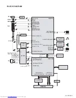
Page 21: ...HS TV_VS 74HC14 CTI LTI SANDC BLOCK DAC CS4335 AUDIO AMPLIFIER 2xTDA7056 HP DRIVER TDA1308 V R G B IN PC_ HS VS YCbCr SYNC SEPARATOR EL1883 Y HD_ HS VS PORTD 5 6 58 57 H V SYNC 65 64 R G B AIN 37 43 50 PORTD7 56 D R G B E 0 7 PORTA7 201 DHS DVS DEN DCLK D R G B O 0 7 RGB MACROVISION YUV VGA _SW A H V SYNC LVDS DS90C385 PANEL UOCIII PW1306 PC in RF in Audio in Audio line out CVBS in R G B OUT Comun...

Page 22: ...2 4 No YA306 ...

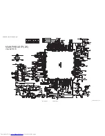
Page 23: ... No YA306 2 5 2 6 No YA306 17mb18 4_0527_1 5_0 0 MAIN PWB ASS Y 1 5 VE 20215170 CIRCUIT DIAGRAMS MAIN PWB CIRCUIT DIAGRAM 1 5 ...

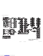
Page 24: ...2 8 No YA306 No YA306 2 7 17mb18 4_0527_2 5_0 0 MAIN PWB ASS Y 2 5 VE 20215170 MAIN PWB CIRCUIT DIAGRAM 2 5 ...

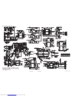
Page 25: ... No YA306 2 9 2 10 No YA306 17mb18 4_0527_3 5_0 0 MAIN PWB ASS Y 3 5 VE 20215170 MAIN PWB CIRCUIT DIAGRAM 3 5 ...

Page 26: ...2 12 No YA306 No YA306 2 11 17mb18 4_0527_4 5_0 0 MAIN PWB ASS Y 4 5 VE 20215170 MAIN PWB CIRCUIT DIAGRAM 4 5 ...

Page 27: ... No YA306 2 13 2 14 No YA306 17mb18 4_0527_5 5_0 0 MAIN PWB ASS Y 5 5 VE 20215170 MAIN PWB CIRCUIT DIAGRAM 5 5 ...

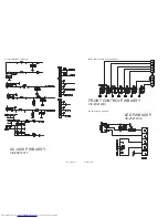
Page 28: ...16 No YA306 No YA306 2 15 AV JACK PWB ASS Y VE 20214317 FRONT CONTROL PWB ASS Y VE 20214331 LED PWB ASS Y VE 20214319 AV JACK PWB CIRCUIT DIAGRAM FRONT CONTROL PWB CIRCUIT DIAGRAM LED PWB CIRCUIT DIAGRAM ...

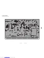
Page 29: ... No YA306 2 17 2 18 No YA306 TOP PATTERN DIAGRAMS MAIN PWB PATTERN SOLDER SIDE ...

Page 30: ...2 20 No YA306 No YA306 2 19 TOP MAIN PWB PATTERN PARTS SIDE ...

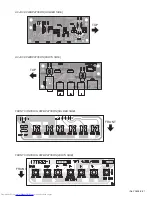
Page 31: ... No YA306 2 21 TOP TOP FRONT FRONT AV JACK PWB PATTERN SOLDER SIDE AV JACK PWB PATTERN PARTS SIDE FRONT CONTEROL PWB PATTERN SOLDER SIDE FRONT CONTEROL PWB PATTERN PARTS SIDE ...

Page 32: ...2 22 No YA306 TOP TOP LED PWB PATTERN SOLDER SIDE LED PWB PATTERN PARTS SIDE ...

Page 33: ... No YA306 AV MULTIMEDIA COMPANY DISPLAY CATEGORY 12 3 chome Moriya cho Kanagawa ku Yokohama city Kanagawa prefecture 221 8528 Japan Victor Company of Japan Limited VPT Printed in Japan ...

Page 34: ...pacitor MF R Metal Film Resistor MF CAP Metalized Film Capacitor MG R Metal Glazed Resistor MM CAP Metalized Mylar Capacitor MP R Metal Plate Resistor MP CAP Metalized Polystyrol Capacitor OM R Metal Oxide Film Resistor PP CAP Polypropylene Capacitor CMF R Coating Metal Film Resistor PS CAP Polystyrol Capacitor UNF R Non Flammable Resistor TF CAP Thin Film Capacitor CH V R Chip Variable Resistor M...

Page 35: ... LENS RIGHT 5 VE 20203832 LENS PRE AMP 6 VE 30041403 SPEAKER 16R 5W 33x105MM x2 7 VE 20182421 FUNCTION BUTTON 8 VE 30026829 LCD PANEL UNIT TFT 4 3 9 VE 35011023 MAIN FRAME 10 VE 30018343 4 CCFL INVERTER UNIT 11 VE 20196634 SCART BRACKET 12 VE 20197261 BACK COVER 13 VE 20183147 FAV BRACKET 14 VE 35012930 HANG METAL x2 15 VE 35011433 METAL HINGE BRACKET 16 VE 20197265 FOOT SUPPORT 17 VE 45004766 MET...

Page 36: ... No YA306 3 3 EXPLODED VIEW 100 103 101 102 9 8 6 1 7 23 2 11 10 15 19 20 24 17 X2 X5 3 4 5 16 18 14 22 21 12 13 ...

Page 37: ...C111 VE 30016654 CAPACITOR 100nF 16V K R C112 VE 30016654 CAPACITOR 100nF 16V K R C113 VE 30016654 CAPACITOR 100nF 16V K R C114 VE 30016654 CAPACITOR 100nF 16V K R C116 VE 30016654 CAPACITOR 100nF 16V K R C117 VE 30016654 CAPACITOR 100nF 16V K R C118 VE 30016654 CAPACITOR 100nF 16V K R C119 VE 30016654 CAPACITOR 100nF 16V K R C120 VE 30016654 CAPACITOR 100nF 16V K R C121 VE 30016654 CAPACITOR 100n...

Page 38: ...VE 30012582 CAPACITOR 10nF 50V K R C339 VE 30016654 CAPACITOR 100nF 16V K R C340 VE 30000393 E CAPACITOR 3 3uF 50V M Ref No Part No Part Name Description Local C341 VE 30016654 CAPACITOR 100nF 16V K R C342 VE 30016654 CAPACITOR 100nF 16V K R C347 VE 30016654 CAPACITOR 100nF 16V K R C349 VE 30012573 CAPACITOR 47pF 50V J C350 VE 30012573 CAPACITOR 47pF 50V J C351 VE 30012573 CAPACITOR 47pF 50V J C35...

Page 39: ...RESISTOR 1 16W 100R J R153 VE 30012510 RESISTOR 1 16W 100R J R154 VE 30012510 RESISTOR 1 16W 100R J R155 VE 30012510 RESISTOR 1 16W 100R J Ref No Part No Part Name Description Local R156 VE 30012692 RESISTOR 1 16W 4 7K J R175 VE 30012641 RESISTOR 1 16W 10K J R176 VE 30012641 RESISTOR 1 16W 10K J R177 VE 30012641 RESISTOR 1 16W 10K J R178 VE 30012641 RESISTOR 1 16W 10K J R179 VE 30012641 RESISTOR 1...

Page 40: ...R509 VE 30012509 RESISTOR 1 16W 100K J R510 VE 30012705 RESISTOR 1 16W 6 8K J R511 VE 30012641 RESISTOR 1 16W 10K J R512 VE 30012669 RESISTOR 1 16W 22K J R513 VE 30012641 RESISTOR 1 16W 10K J R514 VE 30012692 RESISTOR 1 16W 4 7K J R550 VE 30012685 RESISTOR 1 16W 33K J R551 VE 30012685 RESISTOR 1 16W 33K J L100 VE 30001996 FIXED COIL 22uH Q40 K L100 VE 30001971 FERRITE 600R 100MHz 200mA L101 VE 300...

Page 41: ...FERRITE 60R 100MHz 300mA S192 VE 30041653 FERRITE 60R 100MHz 300mA S193 VE 30041653 FERRITE 60R 100MHz 300mA S194 VE 30041653 FERRITE 60R 100MHz 300mA S195 VE 30041653 FERRITE 60R 100MHz 300mA S196 VE 30041653 FERRITE 60R 100MHz 300mA S416 VE 30000469 RESISTOR 1 10W 1K J S417 VE 30000469 RESISTOR 1 10W 1K J SW5 VE 30032684 TACT SWITCH TU200 VE 30029452 TUNER WSP PLL 38 9 HOR IEC L X100 VE 30017946...

Page 42: ...BOX BACK 4 VE 30039453 REMOTE CONTROL UNIT RM C1861 5 VE 30034459 AC ADAPTOR DC12V 4A 6 VE 30002376 POWER CORD For AC ADAPTOR 7 VE 50069375 INST BOOK ENG LT 15B60SJ 7 VE 50069198 INST BOOK ENG GER FRA ITA LT 15B60SW 7 VE 50069199 INST BOOK SPA POR DUT LT 15B60SW 8 VE 50069376 WARRANTY CARD LT 15B60SJ 8 VE 50069200 WARRANTY CARD LT 15B60SW 9 BATTERY AA R06 x2 10 VE 50018337 POLY BAG 1 3 10 2 4 5 6 ...

Reviews: