1-20 (No.MA145)
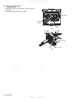
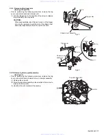
3.2.13 Removing the select arm R / link plate
(See Figs.27 and 28)
• Prior to performing the following procedure, remove the top
plate assembly.
(1) Bring up the select arm R to release from the link plate
(joint a') and turn as shown in the figure to release the two
joints
b'
and joint
c'
.
(2) Move the link plate in the direction of the arrow to release
the joint d'. Remove the link plate spring at the same time.
REFERENCE:
Before removing the link plate, remove the mode sw..
Fig.27
Fig.28
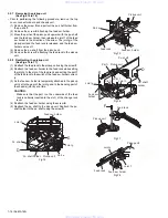
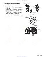
3.2.14 Reattaching the Select arm R / link plate
(See Figs.29 and 30)
REFERENCE:
Reverse the above removing procedure.
(1) Reattach the link plate spring.
(2) Reattach the link plate to the link plate spring while joining
them at joint
d'
.
(3) Reattach the joint a' of the select arm
R
to the first peak of
the link plate while joining the two joints
b'
with the slots.
Then turn the select arm R as shown in the figure. The top
plate is joined to the joint
c'
.
CAUTION:
When reattaching the select arm
R
, check if the points
e'
and
f'
are correctly fitted and if each part operates prop-
Fig.29
Fig.30
Joint r
Link plate
Joint b'
Joint b'
Joint c'
Select arm R
Joint a'
Top plate
Link plate
Link plate spring
Joint d'
Select arm R
Joint c'
Joint d'
Link plate spring
Joint b'
Joint b' Joint a'
Link plate
Joint a'
Point e'
Point f'
www. xiaoyu163. com
QQ 376315150
9
9
2
8
9
4
2
9
8
TEL 13942296513
9
9
2
8
9
4
2
9
8
0
5
1
5
1
3
6
7
3
Q
Q
TEL 13942296513 QQ 376315150 892498299
TEL 13942296513 QQ 376315150 892498299

