(No.MA454<Rev.001>)1-9
SECTION 3
DISASSEMBLY
3.1
Main body (Used figure are KD-AVX77E)
3.1.1 Removing the Top chassis with DVD mechanism (See
Fig.1 to 4)
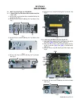
(1) Remove the two screws
A
and two screws
B
attaching the
Heat sink. (See Fig.1)
(2) Remove the one screw
C
attaching the Top chassis. (See
Fig.1)
Fig.1
(3) Remove the one screw
D
attaching the Top chassis. (See
Fig.2)
Fig.2
(4) Remove the three screws
E
attaching the Top chassis.
(See Fig.3)
Fig.3
(5) Remove the two screws
F
attaching the Top chassis. (See
Fig.4)
Fig.4
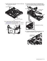
3.1.2 Removing the Main board (See Fig.5 to 10)
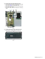
(1) Disconnect the card wire from Front chassis connected to
connector
CN962
of the Main board. (See Fig.5)
(2) Disconnect the connector wire from Gear bracket unit con-
nected to connector
CN881
and
CN891
of the Main board.
(See Fig.5)
(3) Remove the two screws
G
attaching the Main board. (See
Fig.5)
Fig.5
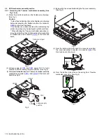
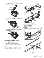
(4) Remove the two screws
H
attaching the Bottom chassis.
(See Fig.6)
Fig.6
B
C
A
D
E
F
F
G
G
CN881
CN891
CN962
H
Summary of Contents for KD-AVX55A
Page 31: ......


