JX-S555(J)
8 (No. 70251)
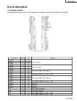
P32
P33
P34
P35
P36
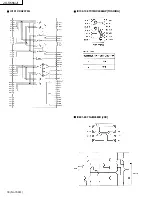
P20/SI30
P21/SO30
P22/SCK30
P23/RxD0
P24/TxD0
P25/ASCK0
V
DD1
AVss
P17/AN17
P16/AN16
P15/AN15
P14/AN14
P13/AN13
P12/AN12
P11/AN11
P10/AN10
AV
REF
AV
DD
RESET
XT2
XT1
IC
X2
X1
Vss
1
P00/INTP0
P01/INTP1
P02/INTP2
P03/INTP3/ADTRT
P70/T100/TO0
P71/TI01
P72/TI50/TO50
P73/TI51/TO51
P74/PCL
P75/BUZ
P64/RD
P65/WR
P66/WAIT
P67/ASTB
21
22
23
24
25
26
27
28
29
30
31
32
33
34
35
36
37
38
39
40
41
42
43
44
45
46
47
48
49
50
51
52
53
54
55
56
57
58
59
60
61
62
63
64
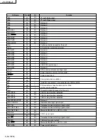
I
2
C path Data signal.
I
2
C path Clock signal
Not used.
Not used.
Not used.
Not used.
Not used.
Not used.
Not used.
Not used.
Not used.
Positive potential (except for the port).
AD converter grounding potential.
Not used.
Not used.
Not used.
Not used.
Not used.
Not used.
CH5 S1/S2 signal input.
Not used.
A/D converter reference voltage input.
Analog power supply for A/D converter
System reset input.
Sub-system clock oscillation.
Internally connected. To be connected to VSS0 or VSS1.
X'tal oscillator connection terminals for Main
system clock oscillation.
Grounding potential (except for the port).
CH3 D4 plug insertion detection.
CH4 D4 plug insertion detection.
CH5 D4 plug insertion detection.
Not used.
Remote control light signal input.
Component video switching signal output.
Component video switching signal output.
Main unit ON/OFF. H = OFF. L = ON.
S1/S2 signal inputs.
Component video switching signal output.
CH5 monitor signal output.
Main unit ON/OFF. H = OFF. L = ON.
Power switch detection.
I/O
I/O
I/O
I/O
I/O
I/O
I/O
I/O
I/O
I/O
I/O
I
—
I
I
I
I
I
I
I
I
I
I
I
—
I
—
—
I
I
I/O
I/O
I/O
I/O
I/O
I/O
I/O
I/O
I/O
I/O
I/O
I/O
I/O
I/O
Pin Name
Pin No.
Function
I/O

