6
-EN
1
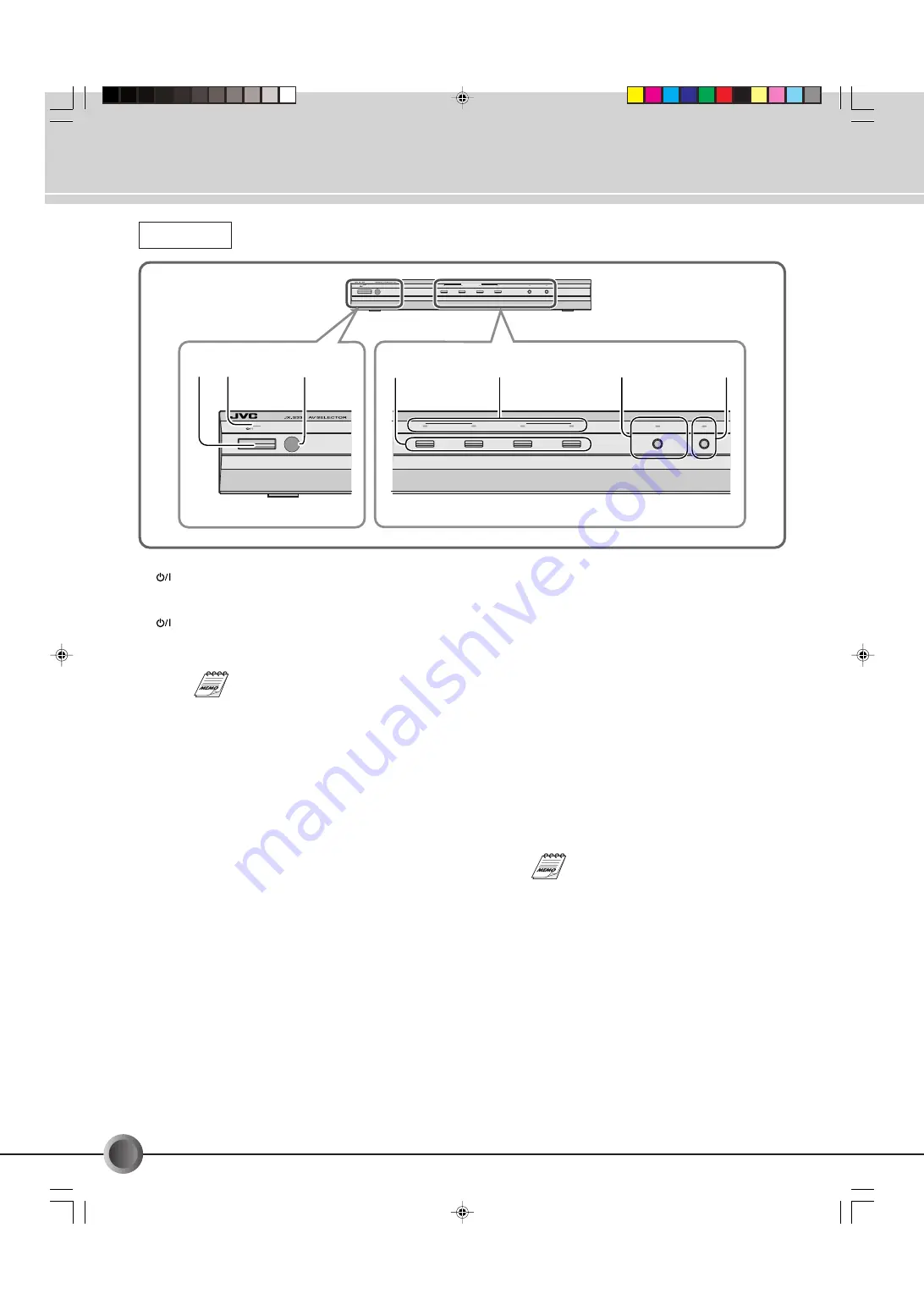
STANDBY/ON button
Press to turn the power ON or OFF (in standby mode).
2
STANDBY/ON indicator
This indicator lights in green when the power is ON, while
it lights in red when the power is OFF (in standby mode).
If the power has been switched OFF to
the Standby mode and then ON again, it
can be operated using the same settings
as when the power was switched OFF.
3
Remote sensor window
Aim at this when operating from the remote control unit.
4
SOURCE SELECT buttons
(
☞
p. 11, 13, 15, 17)
Press to select an input component.
5
SOURCE SELECT indicators
(
☞
p. 11, 13, 15, 17)
The indicator of the input component selected by the
SOURCE SELECT button lights in red.
Connectors, Controls and Indicators
Front View
6
DUBBING LOCK button/indicator
(
☞
p. 15, 17)
(MONITOR SELECT)
Press to fix the output signals through the OUTPUT
1
and
2
connectors. This can prevent accidental or erroneous
operation during dubbing. The indicator lights in red when
DUBBING LOCK is activated.
• When one of the SOURCE SELECT buttons is pressed
while DUBBING LOCK is activated, only the video/audio
output through the MONITOR OUT is changed, but the
video/audio output through the OUTPUT
1
and
2
connectors remains unchanged so that you can keep
dubbing the signals through these connectors.
7
LINK button/indicator
(
☞
p. 20)
Press to turn the LINK function ON or OFF.
When this function is ON, the indicator lights in red. The
unit power automatically turns on or off by detecting the
incoming S-video signals from the playback components.
This function is only available with the
playback components equipped with S-
video output connectors.
STANDBY/ON
1
2
3
4
DUBBING LOCK
LINK
SOURCE SELECT
(MONITOR SELECT)
1
2
3
4
DUBBING LOCK
LINK
SOURCE SELECT
STANDBY/ON
(MONITOR SELECT)
5
4
6
7
1 2
3
JX-S333e.p65
05.2.8, 2:50 PM
6


