background image

ENGLISH

   - 27 -

If you have a device which outputs component

signal, connect it to the EXT-3 terminal with a

component video cable.

Via the ANT (aerial) socket

If your equipment does not have an Eurocon-

nector or RCA jacks, connect it to the TV with

an aerial cable. For details, see the manual

provided with the equipment.
• To store the test signal that comes from the

equipment, see “

Install Menu

” on 

page 17

and store it to the program number 0. You

can  watch  images  from  that  equipment  to

select the program number which you stored

the test signal.

Decoder

Cable  TV  offers  you  a  wide  choice  of

programmes.  Most  of  them  are  free,  others

are to be paid for by the viewer. This means

that you will need to subscribe to the broad-

casting organisation whose programmes you

wish to receive. This organisation will supply

you a corresponding decoder unit to allow the

programmes  to  be  unscrambled.
For further information ask your dealer. See

also the booklet supplied with your decoder.

Connect a decoder with an aerial socket

to the TV

• Connect the aerial cable.

Connect a decoder without an aerial

socket to the TV

•  Connect  the  decoder  to  your  TV  with  a

eurocable (RCA Jack Cable) to 

EXTERNAL

(RCA Jack) (optional). When your decoder

has a Euroconnector / RCA Jack  you  can

obtain better picture quality if you connect a

eurocable (RCA Jack Cable) to 

EXTERNAL

(RCA Jack)


(optional).

TV and Video Recoder (VCR)

• Connect the Video Recorder to the ANT (an-

tenna input) socket of the TV with the aerial

cable.

• Connect the Video Recorder to the 

EXT-1 

or

EXT-2

 terminal with the SCART cable, or con-

nect it to the


EXT-4


terminal with the audio

and video cables.

NTSC Playback

Connect a NTSC video recorder to a terminal.

Then  press  “

AV

”  button  to  select  the  corre-

sponding AV mode.

NTSC 3.58/4.43

 system is detected automati-

cally in AV mode.

Camera and Camcorder

To connect to the


EXT-4

 terminal

Connect your camera or camcorder at the back

side of your TV.
• Connect your equipment to the TV via

 VIDEO

(yellow), 

AUDIO R 

(red) and 

AUDIO L 

(white)

inputs. You should connect the jacks to the

input in the same colour.

Connect the decoder to the video

recorder

Some  video  recorders  have  a  special  euro-

connector for decoder.
• Connect an eurocable to the euroconnector

of your decoder and to the special eurocon-

nector of your video recorder. See also the

handbook of your video recorder.

• To connect your video recorder to the TV, see

TV and Video Recorder section.

If you want to connect more equipment to your

TV, consult your dealer.

Connecting Headphones

Use the stereo headphone socket on the right

side of your TV, to connect headphones.

Connecting the PC

Connect PC monitor with 15-pin PC cable to

the 15-pin connector on the rear of the com-

puter. For detailed installation procedure see

Installation 

in PC mode.

To connect to S-Video input

Connect your camera or camcorder at the back

side of your TV.
• Connect your equipment to the TV via S-Video

input  at  the  back  side  by  using  S-Video

cables.

Summary of Contents for InteriArt LT-26B60BU

Page 1: ...G TÉLÉVISEUR À GRAND ÉCRAN LCD MANUEL D INSTRUCTIONS ITALIANO TV A PIENO SCHERMO LCD ISTRUZIONI LT 26B60BU LT 26B60SU WIDE LCD PANEL TV D GUNCEL IB JVC_LT26B60 BU SU SJ 2625W Grup 1 LT 26B60BU SU GRP1 COVER PAGE 2625W 17MB08P 1860UK LT 26B60BU SU 50074712 cdr 09 Eyl l 2005 Cuma 13 38 08 Color profile Disabled Composite Default screen ...

Page 2: ...id places subject to extremely high temperatures or hu midity or locations where the temperature is likely to fall below 5ºC 41ºF DO ensure that the TV is not standing on the mains lead DO NOT cut off the mains plug from this equipment this incorporates a spe cial Radio Interference Filter the removal of which will impair its performance Hot Moderate Climate Conditions This device is suitable for ...

Page 3: ...leave equipment switched on when it is unattended unless it is specifically stated that it is designed for unattended operation or has a standby mode Switch the equipment off and make sure your family know how to do this Special arrangements may need to be made for infirm or handicapped people DON T continue to operate the equipment if you are in any doubt about it working normally or it is damage...

Page 4: ...inst the TV Doing so may cause the TV to fall over and lead to injuries CAUTION To avoid electric shock or damage to the unit first firmly connect the small end of the power cord to the rear of the TV and then plug the larger end of power cord into an AC outlet CAUTION The TV screen may be damaged if the TV is carried as shown in the diagram The TV should always be carried by two people ...

Page 5: ... business the loss of recorded data whether caused during normal operation or misuse of the product WARNING NEVER LEAVE A STATIONARY IMAGE ON THE SCREEN If stationary images generated by TELETEXT CHANNELIDENTIFICATION LOGOS COM PUTER DISPLAYS VIDEO GAMES ON SCREEN MENUS etc are left on the TV screen for any length of time they could be come permanently ingrained If you use your television to displ...

Page 6: ... PICTURE Mode button YELLOW Sleep Timer button MENU button Cursor Up button OK button Cursor Right button BACK button Volume buttons Teletext VCR DVD Control buttons PC Control Buttons P buttons Cursor Down button Teletext Button Cursor Left button Stereo Bilingual button GREEN Hyper Sound On Off button RED ZOOM Mode button Information Button T V Link in Programme Menu Mute button ...

Page 7: ...s With certain combinations of connectors and leads the back cover may not be easily fitted If the cover is left off this in no way infringes safety requirements 32 5 03 1 5 5 5 9 5 63 5 63 5 67 1 352 5 00 83 2 1 92 80 83 2 1 0 18 79 9 2 3 21 ...

Page 8: ...ENGLISH 7 3 8 2 1 17 11 7 7 3 1387 7 7 8 2 287 7 50 1 3E 3U RPSRQHQW XGLR Q 5 RPSRQHQW XGLR Q 6 9LGHR Q 9LGHR Q XGLR 5 XGLR XGLR 5 XGLR 6XEZRRIHU 2XW 32 5 25 1387 21 2 6 7 9 9 a 32 5 ...

Page 9: ...ENGLISH 8 How to remove the stand Loosen the 5 screws that attach the stand to the TV Gently pull the stand downwards to remove it ...

Page 10: ...l with a sturdy tie using the hook on the back of the TV this will prevent it from falling over Use curtains or blinds to prevent direct sunlight falling on the screen A floor and table top stand are available for this television or and angled bracket which enables the TV to be wall mounted The LCD display panels are manufactured using an extremely high level of precision technol ogy however somet...

Page 11: ...ic 14 9 Zoom 16 9 Zoom 16 9 Zoom Subtitle modes Automatic sound mute when no transmis sion When no valid signal is detected after 5 min utes the TV switches itself automatically to stand by mode NTSC Playback PLL Channel Search TV Picture in PC if PC input available PC input Support Up to 1366 x 768 Audio Lineout BeforeSwitchingonyourTV Power connection IMPORTANT The TV set is designed to oper ate...

Page 12: ...N OFF To switch the TV on Your TV will switch on in two steps 1 Connect the power cord to the system Press the On Off switch at the rear of the TV Then the TV switches itself to stand by mode and the power lamp becomes red located on the front of the TV 2 To switch on the TV from stand by mode either Press the I button on the remote control or on the right side of the TV or Press a digit button on...

Page 13: ...n to exit the menu If you have a T V Link compatible VCR con nected to the EXT 2 terminal press but ton to display T V Link menu Then follow the operating procedure Downloading data to VCR in the following T V Link section T V Link When a T V Link compatible VCR connected to the EXT 2 terminal on the TV it is easier to set up the VCR and to view videos T V Link uses the following features To use T...

Page 14: ... your TV s main power is turned off Set your TV s main power to on StandBy Mode OperatingtheTV You can operate your TV using both the re mote control handset and onset buttons Volume setting and programme selection can be made by using the buttons at the control panel on the right side of the TV Operating with the buttons on the TV Volume Setting Press button to decrease volume or button to increa...

Page 15: ... do not run continuously The fifteenth channel in the list for ex ample may not be channel number 15 but channel number 17 MenuSystem Your TV has been designed with a menu sys tem to provide an easy manipulation of a multi function system The TV is controlled by choos ing the commands which are displayed on the screen MAIN MENU Press the MENU button The main menu will be displayed in the middle of...

Page 16: ...ORXU 7HPS 1RLVH 5HG ULJKW Setting Colour Using or button select Colour Press button to increase colour level Press button to decrease colour level 3LFWXUH RRO 2II 5 6 7 0RGH RQWUDVW ULJKW 6KDUSQHVV RORXU RORXU 7HPS 1RLVH 5HG ULJKW Setting Colour Temp Using or buttonselect ColourTemp Press or button to select Warm Cool or Normal Setting Noise Reduction Using or button select Noise Red Press or butt...

Page 17: ...Level Using or button select Treble Press button to increase treble level Press button to decrease treble level Setting Balance It allows adjusting the distribution between the left and right speakers Using or button select Balance Press button to change balance right ward Press button to change balance leftward Hyper Sound Using or buttonselect Hyper Sound Pressing or button will turn this fea tu...

Page 18: ...the TV goes automatically to stand by mode Child Lock You can use this feature to prevent children turning the TV on off or changing programmes or adjustments etc without remote control Using or button select Child Lock Press button to select Child Lock On or Off When Off is selected there will be no differ ence in the operation of your TV When On is selected the TV can only be controlled by the r...

Page 19: ...s to continue search process To stop the search process when you want press or buttons at any time Decoder EXT 2 You can use this mode to connect any de coder to your TV Press the or buttons to set it On or Off When you select Decoder EXT 2 On EXT 2 output will be chosen as TV mode only and any scrambled channels will be un scrambled through decoder connected your TV via EXT 2 output Setting VCR V...

Page 20: ...tore the channel name To cancel the Name mode press the BLUE button To delete a channel Delete 1 Choose the channel you want to delete 2 Press the YELLOW button to enter the De lete mode 3 Press the YELLOW button to delete it To cancel the Delete mode press the BLUE button To change the programme number of a channel Insert 1 Choose the channel you want to change the programme number 2 Press the GR...

Page 21: ...und Indicator The alternatives of the indicator are Mono Ste reo Dual I and Dual II This indicator is dis played under the programme number indica tor on the screen I II button is used to select Mono or Stereo or Dual I or Dual II 0RQR In Mono broadcast or in forced mono for ste reo broadcast 6WHUHR In Stereo broadcast XDO If dual broadcast detected Dual I is selected in default and also can be se...

Page 22: ...Timer is active the timer stops and if no signal detected again the timer is initialized to 5 minutes and starts 3 seconds later again to count down It is not valid in EXT modes No Signal and Out Of Range Detection PC mode In PC Mode as no menu is displayed in case that there is no PC input to the TV it is dis played an OSD message No input signal detected then the TV will turn to be in PC standby...

Page 23: ...ge the position of the picture in Zoom modes except Full and Regular modes by pressing the or button Note You can only choose REGULAR and FULL in PC mode FULL This uniformly stretches the left and right sides of a normal picture 4 3 aspect ratio to fill the wide TV screen For 16 9 aspect ratio pictures that have been squeezed into a normal picture 4 3 aspect ratio use the FULL mode to restore the ...

Page 24: ...se this item to put the picture into correct place automatically Select Auto position item by using or buttons Press OK button Press MENU buttonor BACK buttontostore the value Warning Auto position adjustment recom mended to be done with the full screen image for the proper adjustment Horizontal Position This item shifts the image horizontally to right hand side or left hand side of the screen Sel...

Page 25: ...3 3LFWXUH RQWUDVW ULJKW RORXU 6KDUSQHVV 5HVHW PIP picture is displayed on the screen with button PIP position is changed by button There are four different PIP positions PIP size is changed by button Two dif ferent PIP sizes are available Programme in the PIP window is increased decreased by digit buttons or AV button All EXT modes except EXT 3 are also available in PIP window PIP window is remove...

Page 26: ...ber using digit buttons The page will be searched and the page number will be displayed on the upper left corner of the screen when the selected page is found Now you can display this tele text page by pressing button To Select Double Height Text Press button for the top half of the infor mation page to be displayed in double height text Press button again for the bottom half of the information pa...

Page 27: ...ion diagrams at the end of this sec tion show you where the different equipment should be connected at the back side of the TV Via the Euroconnector Your TV set has 2 Euroconnector sockets If you want to connect peripherals e g video decoder etc which have Euroconnectors to your TV use SCART input If an external device is connected via the Euroconnector socket the TV is switched to AV mode automat...

Page 28: ...der VCR Connect the Video Recorder to the ANT an tenna input socket of the TV with the aerial cable Connect the Video Recorder to the EXT 1 or EXT 2 terminal with the SCART cable or con nect it to the EXT 4 terminal with the audio and video cables NTSC Playback Connect a NTSC video recorder to a terminal Then press AV button to select the corre sponding AV mode NTSC 3 58 4 43 system is detected au...

Page 29: ...ENGLISH 28 PeripheralEquipmentConnections 17 1 0 25 5 8 2 1 5 9 2 1 1 287 1 2 8 7 DECODER FORSATELLITERECEIVER VIDEO HEADPHONE AUDIO AntennaConnections ...

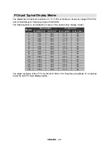
Page 30: ...0 75 Hz and a horizontal sync frequency range of 30 69 KHz The following table is an illustration of some of the typical video display modes RUL RQWDO 9HUWLFDO RU N 9HU 0 RGH UHTXHQF 5 HVROXWLRQ The native resolution of the TFT LCD Panel is 1366 x 768 Therefore using Mode 15 is advised to get the best PC input display quality ...

Page 31: ... of the peripherals No Image on Display Screen Is the aerial connected properly Are the plugs connected tightly to the aerial socket Is the aerial cable damaged Are suitable plugs used to connect the aerial If you are in doubt consult your dealer No Image means that your TV is not receiving any transmission Have you pressed the cor rect buttons on the remote control Try once more PC Picture If no ...

Page 32: ...dcast outputs Video and Audio L R are available EXT 2Terminal Euroconnector 21 pin SCART 2 back of the cabinet Video Input S VIDEO Y C input Audio L R and RGB inputs are available Video and Audio L R outputs are available T V Link functions are available EXT 3Terminal RCA connectors x 5 back of the cabinet Component video Pr Pb Y inputs and Audio L R inputs are available EXT 4Terminal RCA connecto...

Reviews: