background image

24

 EN

S-VHS (Super VHS) and VHS

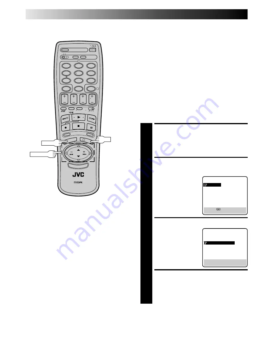
Your recorder can record in either S-VHS or VHS.

To record in S-VHS;

perform the steps 1 – 4 below to set the "S-VHS" to "AUTO".

then, insert a cassette marked "S-VHS", the "S" (S-VHS)
indicator will light on the display panel.

The S-VHS recording mode will be selected.

To record in VHS;

insert a cassette marked "VHS".

The VHS recording mode will be automatically selected
regardless of the S-VHS mode setting.

To record in VHS on an S-VHS cassette;

insert the cassette marked "S-VHS", the "S" (S-VHS) indicator
will light on the display panel.

then, perform the steps 1 – 4 below to set the "S-VHS" to
"OFF"; the "S" (S-VHS) indicator will go out.

The VHS recording mode will be selected.

ACCESS MAIN MENU

SCREEN

1

Press MENU twice.

ACCESS MODE SET

SCREEN

2

Move the highlight bar
(pointer) to "MODE SET"
by pressing PUSH JOG

%fi

, then press OK.

SELECT MODE

3

Move the highlight
(pointer) to "S-VHS" by
pressing PUSH JOG 

%fi

,

then press PUSH JOG    to
select "AUTO" or "OFF".

RETURN TO NORMAL

SCREEN

4

Press MENU.

MAIN MENU

MODE SET

AUTO CH SET
MANUAL CH SET
GUIDE PROG SET
CLOCK SET
LANGUAGE SET
JLIP ID NO. SET
R.A. EDIT

[

5∞

=

[MENU] : EXIT

5

%

MODE SET

AUTO TIMER : OFF
O. S. D.

: ON

S-VHS

: AUTO

EDIT

: OFF

TIME SCAN

: ON

AUDIO

[

5∞

=

 [   ] : AUTO/OFF

[MENU] : EXIT

1

2

4

5

3

6

8

0

7

9

2

4

1

3

RECORDING (cont.)

MENU

PUSH JOG

NOTE:

When playing back a tape that has been recorded in S-VHS, the
S-VHS indicator lights on the display panel regardless of the
"S-VHS" mode setting.

OK

Summary of Contents for HR-S9400EE

Page 1: ...L SETTINGS 8 Auto Set Up 8 Language Set 9 Video Channel Set 10 Clock Set 12 On Screen Displays 13 PLAYBACK 14 Basic Playback 14 Playback Features 15 TimeScan 20 RECORDING 22 Basic Recording 22 Recording Features 23 INFORMATION ON SIGNAL CONVERSION SYSTEM 26 TIMER RECORDING 28 SHOWVIEW Setup 28 SHOWVIEW Timer Recording 30 Regular Timer Programming 32 SPECIAL FEATURES 36 TV Multi Brand Remote Contro...

Page 2: ...emove the power cord from the mains outlet prior to connecting or disconnecting any signal lead or aerial This recorder can also receive SECAM colour television signals for recording and playback POWER SYSTEM This set operates on voltage of AC 220 240 V Rating AC 180 260 V Operating 50 60 Hz with automatic switching The STANDBY ON button does not com pletely shut off mains power from the unit but ...

Page 3: ... top of the recorder or remote control 5 AVOID violent shocks to the recorder during transport MOISTURE CONDENSATION Moisture in the air will condense on the recorder when you move it from a cold place to a warm place or under extremely humid conditions just as water droplets form in the surface of a glass filled with cold liquid Moisture condensation on the head drum will cause damage to the tape...

Page 4: ...onnect the provided RF cable between the RF OUT jack on the rear panel of the recorder and the TV s aerial connector Before operating the recorder make sure the TV s channel is set to the VIDEO channel Z pg 10 AV CONNECTION To Connect To A TV with 21 pin AV input connector SCART a Connect the aerial recorder and TV as per RF CONNECTION b Connect an optional SCART cable between the AV1 IN OUT conne...

Page 5: ...composite signal regular video signal but can deliver either a composite video signal or a Y C signal a signal in which the luminance and chrominance signals are separated according to the setting of the rear panel AV1 OUT switch If your TV s 21 pin AV input connector SCART is compatible only with the regular video signal set this switch to COMP If your TV s 21 pin AV input connector SCART is comp...

Page 6: ...ts with an S VIDEO input terminal S VIDEO Connection IMPORTANT To operate the recorder with your TV using the S VIDEO connection set your TV to the VIDEO or AV mode AUDIO OUT Mains outlet Mains Power Cord Audio cable provided ANT IN RF OUT S OUT After you plug the mains power cord into a mains outlet the Auto Set Up display appears on the TV screen and or on the recorder s front display panel when...

Page 7: ...EN 7 RF Cable provided Back of TV S Video cable provided Back of Recorder Aerial ...

Page 8: ...cted your TV to the recorder with RF connection and the on screen display appearing on UHF channel 36 looks distorted refer to the front display panel If you want to set the tuner manually such as to add or skip channels to swap channel positions to fine tune channels or to set station names ID Z p 55 Z pg 52 55 If no sound accompanies the picture on some channels that have been stored by Auto Set...

Page 9: ...3 6 8 0 7 9 2 4 1 3 PUSH JOG MENU OK TURN ON THE RECORDER 1 Press ACCESS MAIN MENU 2 Press MENU twice ACCESS LANGUAGE SET SCREEN 3 Press PUSH JOG fi to move the highlight bar pointer to ВЫБОР ЯЗЫКА LANGUAGE SET then press OK SELECT LANGUAGE 4 Press PUSH JOG fi to move the highlight bar pointer to the language of your choice RETURN TO NORMAL SCREEN 5 Press MENU ГЛАВНОЕ МЕНЮ УСТАНОВКА РЕЖИМОВ АВТОУС...

Page 10: ...he two vertical white bars appear clearly on the screen as shown in the illustration at bottom left press OK and then go to step 3 If the two vertical white bars do not appear clearly press TV PROG or to set the video recorder to a vacant channel between 22 and 69 which is not occupied by any local station in your area Then set your TV to UHF channel 50 and check if the two vertical white bars app...

Page 11: ...ngolia Rumania Bulgaria Czech Rep Slovakia Hungary Poland D K Russia IMPORTANT Before performing the following steps make sure the recorder s power is off and there is no cassette inserted in the recorder ACCESS VIDEO CHANNEL SET MODE 1 Hold down STOP EJECT on the recorder until the display panel shows the following SET VIDEO CHANNEL 2 Press TV PROG until the display panel shows OUT Now the video ...

Page 12: ...Repeat the proce dure to set the minutes day month and year START CLOCK OPERATION 5 Press MENU MAIN MENU MODE SET AUTO CH SET MANUAL CH SET GUIDE PROG SET CLOCK SET LANGUAGE SET JLIP ID NO SET R A EDIT 5 MENU EXIT CLOCK SET TIME DATE YEAR 0 00 01 01 00 5 MENU EXIT INITIAL SETTINGS cont NOTES If the day and month data are invalid such as 31st April the month digits are cleared automatically and the...

Page 13: ...before starting During playback the operation mode indicators may be disturbed depending on the type of tape being used 1 Operation mode indicators 2 Channel position number and station name Aux indicator AUX1 AUX2 or F AUX Displayed only if you have set manually Z pg 54 3 Cassette loaded mark 4 Tape speed SP LP 5 Clock display 6 Current day month year 7 SpatializerW indicator Z pg 18 8 Tape direc...

Page 14: ... ring to the left To go forward press FF or turn the TIME SCAN SHUTTLE ring to the right START PLAYBACK 3 Press PLAY STOP PLAYBACK 4 Press STOP on the remote or STOP EJECT on the recorder s front panel Then press STOP EJECT to remove the cassette Usable cassettes Compact VHS camcorder recordings can be played on this video recorder Simply place the recorded cassette into a VHS Cassette Adapter and...

Page 15: ...irection To play in reverse slow motion and in reverse play mode continue to turn the TIME SCAN SHUTTLE ring to the left or press PUSH JOG after selecting all the forward direction slow motion modes OR During still picture turn the TIME SCAN SHUTTLE ring to the right for forward slow motion or to the left for reverse slow motion OR During still picture press and hold PAUSE for 2 seconds then relea...

Page 16: ...1 3 REW FF TV PROG PLAY REVIEW PUSH JOG Tape Position Indicator The tape position indicator appears on screen when from the Stop mode you press FF REW or perform an Index Search The position of 5 in relation to 0 beginning or end shows you where you are on the tape O S D Z pg 13 must be set to ON or the indicator will not appear NOTE Depending on the type of tape used there may be times when the i...

Page 17: ...REVIEW and 3 appear and blink To watch the first of the 3 programmes press REVIEW three times The recorder searches and begins playback automatically You can access a programme as far as 9 index codes away from the current tape position NOTE Instant ReView is not possible while the recorder is in the Timer mode 2 MESECAM Playback Your recorder is equipped with MESECAM circuitry that can play back ...

Page 18: ...h a stereo TV You can change the SpatializerW setting even though O S D is set to OFF The setting cannot be changed during search still frame by frame playback or slow motion mode When this recorder is used as the player for editing the recorded audio will correspond to the SpatializerW setting 1 2 4 5 3 6 8 0 7 9 2 4 1 3 C M E M O R Y A B CODE FF C RESET REW AUDIO MONITOR S T O P SCENE FINDER STO...

Page 19: ...l is preset to send A code signals because your video recorder is initially set to respond to A code signals You can easily modify your video recorder to respond to B code signals REMOVE POWER SUPPLY 1 Unplug the mains power cord from the mains outlet SET A B CODE SWITCH 2 Set to B RE SUPPLY POWER 3 Plug the mains power cord back into the mains outlet TURN THE RECORDER ON 4 Press on the remote con...

Page 20: ...t be played so that the audio can keep up with the video 1 2 3 4 5 Audio signal during TimeScan Sound of 1 3 and 5 is heard Sound of 2 and 4 is not heard Output audio signal is normal monaural sound Playback tape ACTIVATE VARIABLE SPEED SEARCH 1 During playback or still turn the recorder s TIME SCAN SHUTTLE ring It remains at that position even after you release it Each time it passes a click posi...

Page 21: ...ay appear or the upper part of the picture may be distorted during still frame by frame playback 2x search of LP recordings or depending on the tape being used Depending on the type of TV being used the upper part of the picture may be distorted or there may be a loss of colour during still frame by frame playback 2x search of LP recordings or depending on the tape being used Picture may appear di...

Page 22: ...y panel to confirm the selected tape speed START RECORDING 4 Press and hold RECORD and press PLAY on the remote control or press RECORD on the recorder PAUSE RESUME RECORDING 5 Press PAUSE Press PLAY to resume recording STOP RECORDING 6 Press STOP on the remote control or STOP EJECT on the recorder Then press STOP EJECT to remove the cassette Turn on the TV and select the VIDEO channel or AV mode ...

Page 23: ... Each press extends recording time by 30 minutes NOTE You can only perform ITR using the RECORD button on the recorder s front panel Elapsed Recording Time Indication You can check the exact time of a recording SET COUNTER DISPLAY 1 Press DISPLAY until a counter reading appears on the dispay panel By pressing the DISPLAY button you can change the display to show the counter reading channel positio...

Page 24: ...FF the S S VHS indicator will go out The VHS recording mode will be selected ACCESS MAIN MENU SCREEN 1 Press MENU twice ACCESS MODE SET SCREEN 2 Move the highlight bar pointer to MODE SET by pressing PUSH JOG fi then press OK SELECT MODE 3 Move the highlight pointer to S VHS by pressing PUSH JOG fi then press PUSH JOG to select AUTO or OFF RETURN TO NORMAL SCREEN 4 Press MENU MAIN MENU MODE SET AU...

Page 25: ...ry results If necessary you can adjust the Hi Fi audio recording level more precisely by reffering to the audio level indicator on the front panel Retake You can cut out unnecessary parts of a TV programme while you re recording it End of programme Programme Beginning of programme Programme Recorded part RESUME RECORDING 3 Press PLAY when you wish to resume recording ENGAGE RECORD PAUSE MODE 1 Pre...

Page 26: ...ert the playback signals when you wish to view a SECAM tape on a PAL TV If you set the OUTPUT SYSTEM CONVERTER switch to OFF the output signals will be the same as the one recorded on the cassette The output signal will also be converted when you are watching a programme during recording If you are using a dual system PAL SECAM TV it is recommendable not to convert the playback signals with your v...

Page 27: ...e with this recorder Input Signal REC SYSTEM Switch Type of Tape Recording Speed Recorded Signal on the Tape VHS SP SECAM AUTO LP PAL S VHS SP PAL LP PAL VHS SP SECAM SECAM SECAM VHS LP PAL S VHS SP PAL LP PAL VHS SP PAL PAL LP PAL S VHS SP PAL LP PAL VHS SP PAL AUTO LP PAL S VHS SP PAL LP PAL VHS SP SECAM PAL SECAM VHS LP PAL S VHS SP PAL LP PAL VHS SP PAL PAL LP PAL S VHS SP PAL LP PAL ...

Page 28: ...uner setting Z pg 8 51 Clock setting Z pg 12 SHOWVIEW Setup TIMER RECORDING IMPORTANT Perform the following procedure after Auto Set Up on page 8 and or the channel setting steps on pages 51 54 After setting the Guide Program Numbers channel positions may be incorrect if you stored or skipped channels In this case re perform Guide Program Number setting Guide Program Number Set MAKE LIST OF STORED...

Page 29: ... number of a program that has already aired ERROR appears on screen for a few seconds Input the correct SHOWVIEW number Repeat steps 5 and 6 as necessary CLOSE MENU 7 Press MENU and selection is complete MAIN MENU MODE SET AUTO CH SET MANUAL CH SET GUIDE PROG SET CLOCK SET LANGUAGE SET JLIP ID NO SET R A EDIT 5 MENU EXIT 5 GUIDE PROG SET GUIDE PROG TV PROG 1 AUTO SET BY SHOWVIEW MANUAL SET 5 MENU ...

Page 30: ...gramme stop time then the date and channel position IMPORTANT Be sure to confirm the setting of VPS recording If ON is displayed on the screen or is lit on the display panel VPS is set to ON If OFF is displayed on the screen or is not lit on the display panel VPS is set to OFF To change the setting press VPS NUMBER key 7 Z VPS Recording on page 35 1 2 4 5 3 6 8 0 7 9 2 4 1 3 NUMBER OK CANCEL Befor...

Page 31: ... programme the recorder to record a ninth PROGRAM FULL appears on screen and FULL appears on the front display panel To record the extra programme you must first cancel any unnecessary programmes Z pg 34 ATTENTION Regarding Guide Program Number Set ERROR GUIDE PROG appears after performing step 3 on the previous page if the Guide Program number for the SHOWVIEW number you entered has not been set ...

Page 32: ...2 MENU EXIT SP ACCESS TIMER PROGRAMMING SCREEN 1 Press PROG ACCESS PROGRAMME SCREEN 2 Press START If you re just starting out P1 appears The front display panel looks like this ENTER PROGRAMME START TIME 3 Press START to enter the time you want recording to start Press and hold START to move in 30 minute increments or press and release repeatedly to move 1 minute at a time The front display panel ...

Page 33: ...y 8 for daily serials Monday Friday Either WEEKLY or DAILY appears on the screen Pressing the button again makes the corresponding indication disappear SP P1 START STOP 21 00 22 00 SP ON DATE TV PROG 25 12 1 MENU EXIT D A I L Y WEEKLY TIMER OK TV PROG NOTE You can programme this recorder to timer record as many as 8 programmes If you try to programme the recorder to record a ninth PROGRAM FULL app...

Page 34: ... the display to the programme stop time then the date and channel position If the recorder is turned on and the TV is set to its VIDEO channel or AV mode you can check program information on screen Each time you press PROG CHECK the next programme s information appears If All Information Is Correct programming is completed If You Wish To Revise Data with the recorder s power turned on go to step 2...

Page 35: ...em is connected to the AV2 IN connector on your recorder VPS recording is also possible via the AV1 IN OUT connector and the front panel connectors How to check if the station being received transmits a VPS signal 1 Press DISPLAY until the channel position appears on the display panel 2 Hold down START for about 5 seconds appears blinking on the display panel If a VPS signal is detected from the s...

Page 36: ...control With televisions under Code 01 11 or 12 the PUSH JOG button corresponds to the 10 button and the PUSH JOG button corresponds to the 20 button of your TV s remote control With televisions using Code 12 the DISPLAY button corresponds to the 30 button With televisions using Code 09 the OK button corre sponds to the ENTER button of your TV s remote control NOTE The way these buttons are used i...

Page 37: ...TRY OPERATING SATELLITE TUNER 2 Press on the remote to turn the satellite tuner off If it goes off try other operations The button TV PROG button NUMBER buttons on the remote can all be used to operate the satellite tuner The NUMBER buttons will not work with JVC satellite tuners using code 13 With satellite tuners using Code 16 the button corresponds to the ENTER button of your satellite tuner s ...

Page 38: ...O EDIT ON TIME SCAN ON AUDIO 5 ON OFF MENU EXIT NOTE After you finish editing be sure to set EDIT back to OFF Advantages Of S VHS Video Recorders EDITING You can edit from VHS to S VHS S VHS to VHS or from S VHS to S VHS From VHS to S VHS VIDEO VIDEO connection Record VHS playback signals in the S VHS mode Although the picture quality is inherently limited by that of the original the edited tape h...

Page 39: ...anel input connectors Connector NOTES Connections made to the front panel Video and Audio inputs automatically override the rear panel AUDIO VIDEO input connection If you wish to edit with another machine connected to the rear input connector make sure that there is nothing connected to the front connectors Use the L connector for monaural connection When using rear panel input connectors AU 1 AU ...

Page 40: ... recorder with S Video and Audio input output connectors you can connect them to this recorder s S IN S OUT and AUDIO IN OUT connectors SET RECORDING DECK S INPUT MODE 2 Set to AUX When using this recorder as the recording deck select the appropriate input mode Z To Select The External Input Mode on page 39 SET EDIT MODE 3 See Editing Mode Setting on page 38 START SOURCE PLAYER 4 Engage its Play m...

Page 41: ...ded Another recorder Recorder Player Recorder Your recorder TV Receiver TV Receiver Player Your recorder If another recorder has no 21 pin SCART connector When connecting the AV cable use the input and or output cable adapter as illustrated below Output cable adapter not provided Audio Cable provided Video Cable not provided VIDEO CHAN NEL or AV mode VIDEO CHAN NEL or AV mode RF Cable provided Out...

Page 42: ...operating procedure SET RECORDER S INPUT MODE 2 Press NUMBER key 0 or TV PROG so that F AU appears in place of a channel position number Refer to To Select The External Input Mode on page 39 SET EDIT MODE 3 See Editing Mode Setting on page 38 START CAMCORDER 4 Engage its Play mode START RECORDER 5 Engage its Record mode EDITING cont NOTE Be sure to set EDIT back to OFF when you finish editing Z pg...

Page 43: ...AY to start the tape in your recorder Audio dubbing begins at this point blinks and is displayed on the front display panel To stop dubbing temporarily press PAUSE Press PLAY to resume dubbing END AUDIO DUBBING 6 Press STOP EJECT to stop the tape in your recorder and engage the audio component s Stop mode Audio dubbed tape CD Player etc Pre recorded tape Normal audio track Video Hi Fi audio track ...

Page 44: ... 39 LOCATE END POINT 3 Load the recording cassette into your recorder and play it back to determine the edit out point the end of the segment to be replaced using the JOG TIME SCAN SHUTTLE controls or PUSH JOG and PAUSE RESET THE COUNTER 4 Press C RESET to change the counter display to 0 00 00 LOCATE START POINT 5 Determine the edit in point the beginning of the segment to be replaced using the JO...

Page 45: ...ure Hi Fi audio soundtrack and normal audio soundtrack all at the same time In step 6 above after you press INSERT press A DUB also and blink and lights up on the front display panel 1 2 4 5 3 6 8 0 7 9 2 4 1 3 8 NOTES Suitable leads can be obtained from your dealer Insert editing is not possible with cassettes whose safety tab has been removed When insert editing is performed on a tape that has b...

Page 46: ...corder s PAUSE R A EDIT connector to the PAUSE connector on the recording deck If the recording deck doesn t have a PAUSE connec tor connect to the R A EDIT connector instead The Mini plug cable is a mono 3 5 mm mini plug to mono 3 5 mm mini plug connector PREPARE FOR EDITING 2 Insert the cassette to be recorded on into the recorder and set the recorder s input mode LOAD SOURCE CASSETTE 3 Insert t...

Page 47: ... for but disappears during actual editing During scene search the recording deck automati cally enters its Record Standby mode When all registered scenes have been edited your recorder enters the Pause mode the recording deck enters its Record Standby mode and the cursor blinks at the next available number fi 1 2 3 4 5 6 7 8 0 00 00 0 00 00 MENU EXIT 1 0 02 23 2 3 4 5 6 7 8 0 02 23 0 00 00 MENU EX...

Page 48: ... prerolls during Random Assemble Editing there must be at least 15 seconds worth of recorded material prior to any edit in point on the source tape If the search time for an edit in point exceeds 5 minutes the recording deck enters its Stop mode and editing will not take place During steps 8 and 9 if you engage the Pause mode while registering edit in and out points in the R A Edit screen the char...

Page 49: ...her device via its J terminal The ID Number is preset to 1 at the factory You can change this number to any number between 1 and 99 If it is necessary to change the JLIP ID number perform the following steps 1 2 4 5 3 6 8 0 7 9 2 4 1 3 8 OK MENU PUSH JOG ATTENTION After you change your recorder s JLIP ID number control signal transmission may not work properly If this happens turn off the recorder...

Page 50: ...ugh a stereo amplifier A sudden surge in the input level to the speakers may damage them Some speakers and televisions are specially shielded to prevent television interference If both are of the non shielded type do not place the speakers adjacent to the TV set as this can adversely affect the video playback picture NOTES When connecting your recorder s audio output connectors to a stereo amplifi...

Page 51: ...g steps only if auto channel set has not been set correctly by Auto Set Up function Z pg 8 or if you have moved to a different area or if a new station starts broadcasting in your area Your recorder needs to memorise all necessary stations in channel positions in order to record TV programmes Auto Channel Set automatically assigns all receivable stations in your area so that you can call them up w...

Page 52: ...OG fi While tuning F or F appears If necessary to change the band between CH regular and CC cable press PUSH JOG until CH or CC is blinking then press PUSH JOG fi to select the band ENTER NEW CHANNEL INFORMATION 5 Press OK and the Confirmation screen appears Repeat steps 3 through 5 as necessary CLOSE CONFIRMATION SCREEN 6 Press MENU To input the station name see page 54 To change positions see Ch...

Page 53: ...ve the station to the new channel position then press OK Example If you moved the station in position 3 to position 7 the stations originally in positions 4 7 each move up one space Repeat steps 1 and 2 as necessary CLOSE CONFIRMATION SCREEN 3 Press MENU TV System Selection When you see the picture but hear no audio Perform steps 1 and 2 of Storing Channels Manually on page 52 to access the Confir...

Page 54: ...ge 52 to access the Confirmation screen and then perform step 1 of Set Stations A above before continuing Set Stations B Perform steps 1 and 2 of Storing Channels Manually on page 52 to access the Confirmation screen before continuing SELECT CHANNEL TO FINE TUNE 1 Press PUSH JOG fi until the channel you want to tune begins blinking ACCESS MANUAL CH SET SCREEN 2 Press OK three times The Manual Ch S...

Page 55: ...N ORF1 ORF1 ID STATION NAME ORF2 ORF2 ORF3 ORF3 OWL3 OWL3 PREM PREMIERE PRO7 PRO7 RAI1 RAI1 RAI2 RAI2 RAI3 RAI3 RET4 RETE4 21 TELE21 RTBF RTBF1 or 2 RTL RTL RTL2 RTL2 RTL4 RTL4 RTL5 RTL5 RTP RTP S4 SCHWEIZ4 SAT1 SAT1 SBS SBS SHOW SHOW SIC SOCIEDADE SKY SKY CHANNEL SKYN SKY NEWS SPRT SPORT SRTL SUPER RTL STAR STAR TV SVT1 SVT1 SVT2 SVT2 SW3 SUEDWEST3 TCC TCC TELE TELE TEL5 TELE5 TF1 TF1 TM3 TM3 TMC...

Page 56: ... tape is running 2 Noise appears during normal playback 3 Noise appears during slow motion playback 4 Noise appears during still play back 5 Breaks are noticeable in Hi Fi soundtrack 6 The playback picture is blurred or interrupted while TV broadcasts are clear 7 No sound accompanies the playback picture with RF connection POSSIBLE CAUSE If you re using the RF OUT connec tion the TV receiver s cha...

Page 57: ...or cover the hole using adhesive tape Remove the cassette and cover the hole with adhesive tape or insert a cassette with the Record Safety tab intact Check the programmed data and re program as necessary then press TIMER again The programme may not have been recorded in its entirety Next time make sure you have enough time on the tape to record the entire programme Refer to SHOWVIEW Setup and re ...

Page 58: ...pg 8 SYMPTOM 1 Whistling or howling is heard from the TV during camcorder record ing 2 When scanning channels some of them are skipped over 3 The channel cannot be changed 4 Channel settings that were made manually seem to have changed or disappeared 5 No channels are stored in the recorder s memory POSSIBLE CAUSE The camcorder s microphone is too close to the TV The TV s volume is too high Those ...

Page 59: ...ation of recording Why does this happen A This is normal It reduces distortion at the pause and resume points Q Can the video recorder indefinitely remain in the Record Pause mode A No The video recorder goes to its Stop mode auto matically after 5 minutes to protect the heads Q What happens if the tape runs out during recording A The video recorder automatically rewinds it to the beginning TIMER ...

Page 60: ... Button Z pg 43 8INSERT Button Z pg 45 9OUTPUT SYSTEM CONVERTER Switch Z pg 26 0Cassette Loading Slot STOP EJECT Button Z pg 14 PLAY Button Z pg 14 TIME SCAN Indicator Z pg 20 TIME SCAN SHUTTLE Ring Z pg 20 TV PROG Dial Z pg 22 JOG Dial Z pg 15 HEADPHONE Connector It is possible to listen to the audio using headphones Adjust the volume level using the Headphone Volume Control HEADPHONE VOLUME Cont...

Page 61: ...IEW Indicator Z pg 17 9 Audio Mode Indicator Z pg 18 0 Cassette Loaded Mark Tape Speed Indicators Z pg 22 Tape Remaining Time Indicator Z pg 23 Counter Remain Display Z pg 23 7 AUDIO IN L R Connectors Z pg 50 8 AUDIO OUT L R Connectors Z pg 50 9 AV2 IN Connector Z pg 40 0 Remote PAUSE Connector Z pg 42 R A EDIT Connector Z pg 46 RF OUT Connector Z pg 4 1 Mains Power Cord Z pg 4 2 S Video IN Connec...

Page 62: ...tton Z pg 22 SCENE FINDER Button Z pg 19 PROG MENU Button Z pg 9 30 PUSH JOG fi Button Z pg 9 PUSH JOG Button Z pg 15 17 36 STANDBY ON Button Z pg 8 DISPLAY Button Z pg 23 ADD TIME Button Z pg 31 DAILY Button Z pg 31 33 qWEEKLY Button Z pg 31 33 wAUX Button Z pg 39 eTIMER Button Z pg 31 33 rTV PROG Button Z pg 22 tDATE Button Z pg 32 yTV SAT VCR Switch Z pg 36 37 uTV VCR Button Z pg 36 iFast Forwa...

Page 63: ...AL 240 lines VHS SECAM Frequency range 70 Hz to 10 000 Hz Normal audio 20 Hz to 20 000 Hz Hi Fi audio Input Output 21 pin SCART connectors IN OUT x 1 IN x 1 RCA connectors VIDEO IN x 1 AUDIO IN x 2 AUDIO OUT x 1 S Video connectors IN x 1 OUT x 1 TUNER TIMER TV channel storage capacity 99 positions AUX position AU Tuning system Frequency synthesized tuner Channel coverage VHF 47 100 104 300 302 470...

Page 64: ...EN COPYRIGHT 1997 VICTOR COMPANY OF JAPAN LTD EE Printed in Japan 1097HOV UN VP VICTOR COMPANY OF JAPAN LIMITED HR S9400EE ...

Reviews: