Page 5
November 11, 2002 2:09 pm
— 5 —
Remote
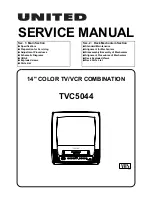
On-screen display
If you press
OSD (OK)
on the Remote when “SUPERIMPOSE” is
set to “ON”(
墌
pg. 12), you can see the current VCR status on the
TV screen. Press
OSD (OK)
again to exit on-screen display.
The indications are not recorded even if the VCR is in the
recording mode.
A
Channel and auxiliary input
B
Day and clock time
C
STEREO program indication
D
SAP indication
E
Audio monitor indications
F
Time counter
G
Index number
H
Tape position
I
Cassette mark
J
Tape speed
K
VCR operation mode
L
Timer warning display
Connections and
Plug&Play Setting
A
Check contents
Make sure the package contains all of the accessories listed in
“Specifications” (
墌
pg. 14).
B
Situate VCR
Place the VCR on a stable, horizontal surface.
C
Connect VCR to TV
RF Connection
A
Disconnect the TV antenna from the TV.
B
Connect the TV antenna cable to the ANT. IN terminal on the
rear of the VCR.
C
Connect the supplied RF cable between the TV OUT terminal
on the rear of the VCR and the TV’s antenna input terminal.
AV Connection
(improves picture quality during tape playback.)
If your TV is equipped with audio/video input connectors
A
Connect the antenna, VCR and TV as shown in the illustration.
B
Connect an audio/video cable between the AUDIO/VIDEO
OUT connectors on the rear of the VCR and the audio/video
input connectors on the TV.
●
Even if you are using audio/video cables to connect your VCR to
your TV, you must also connect it using the RF cable. This will
ensure that you can record one show while watching another.
* Depending on type of matching transformer, it can not be connected to
ANT. IN terminal when connecting Audio/Video cable to AUDIO/VIDEO
OUT connectors.
TIMER
CANCEL
B
+
+
+
E
CH125
RECORD
THU
12:00 AM
PAUSE
STEREO –WARNING–
SP
SAP
TIMER RECORDING
TO START SOON
(CANCEL)
INDEX 1
NORM
HI-FI
COUNT
–1:23:45
A
B
C
D
E
K
J
I
H
G
F
L
RF cable
(supplied)
Back of VCR
Flat feeder
AC power cord
Audio/video cable
(not supplied)
To audio/video
input connectors
Antenna or cable
Matching transformer
(not supplied)
Coaxial cable
AC outlet
To 75
⍀
terminal
TV
– Buttons, Connectors and Indicators –
CONTINUED ON NEXT PAGE
HR-J692U-1.fm Page 5 Monday, November 11, 2002 2:10 PM