(No.YF376<Rev.001>)1-19
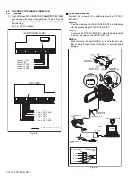
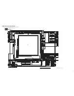
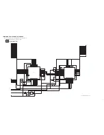
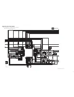
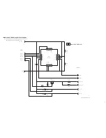
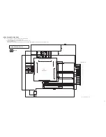
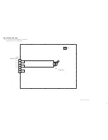
Jig connector diagrams
Fig.4-2-3
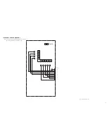
Conversion Connector
Fig.4-2-4
4.3
ELECTRICAL ADJUSTMENT
Electrical adjustment is performed by using a personal computer and software for SERVICE SUPPORT SYSTEM. Read
README.TXT file to use the software properly.
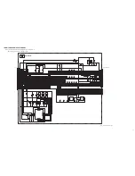
As for the connection of cables, see "4.2 JIG CONNECTOR CABLE CONNECTION".
4.4
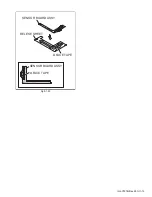
IDE ADAPTER AND FPC WIRE
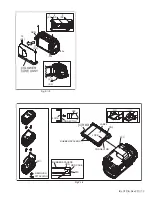
• IDE ADAPTER and FPC WIRE are used for HDD test.
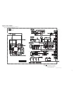
Check with the NOTE, and then refer to the below figure (Fig. 4-4-1) for the connection procedure.
Fig.4-4-1
<NOTE>
• During the procedure, be careful in handling the parts. Pay special attention not to give any external shock to the HDD.
• There are two types of IDE ADAPTER (Parts Number: YTU96041, YTU96043). Either type can be used.
• Using the FPC WIRE originally used with this unit will damage the HDD.
Use the FPC WIRE (Parts Number: YTU94165-40) to connect the IDE ADAPTER and the HDD.
Connecting the FPC WIRE upside-down will damage the HDD.
13. IF_TX
28. IF_RX
20
19
18
17
16
15
14
13
12
11
DSP_RTCK
DSP_TMS
XDSPSRST
XDSPTRST
REG_2.83V
OCD_SDA
SYS_RSTL
GND
DSP_TDI
GND
UA_RXD0
UA_TXD0
DSP_TCK
OCD_SCL
IF_RX
IF_TX
AL_2.83V
IRU
KENTO
DSP_TDO
-
AL_2.83V
IF_RX
-
-
-
-
-
-
-
NC
NC
NC
NC
NC
-
-
IF_TX
-
-
GND
GND
-
-
-
NC
NC
NC
NC
NC
10
9
8
7
6
5
4
3
2
1
30
29
28
27
26
25
24
23
22
21
20
19
18
17
16
15
14
13
12
11
10
9
8
7
6
5
4
3
2
1
MAIN CN110
JIG CONN. BOARD
(PIN NO.)
ADDITIONAL WIRE
JIG CONNECTOR CABLE (YTU93106B)
15
14
13
12
11
10
9
8
7
6
5
4
3
2
1
KENTO*
AL_2.83V
IF_RX
DSP_TCK*
UA_RXD0*
DSP_TDI*
SYS_RSTL*
REG_2.83V*
XDSPSRST*
DSP_RTCK*
NC
NC
NC
NC
NC
1
2
3
4
5
6
7
8
9
10
30
29
28
27
26
25
24
23
22
21
20
19
18
17
16
11
12
13
14
15
16
17
18
19
20
DSP_TDO*
IRU*
IF_TX
OCD_SCL*
UA_TXD0*
GND
GND
OCD_SDA*
XDSPTRST*
DSP_TMS*
NC
NC
NC
NC
NC
*NOT USED
HDD
HDD
IDE ADAPTER
CONNECTOR
<BACK SIDE>
<FRONT SIDE>
FPC WIRE(Parts No.:YTU94165-40)
LABEL

