background image

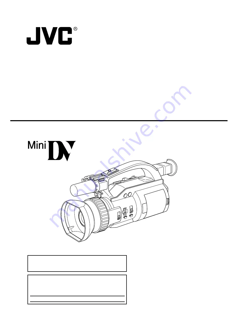
GY-DV300

INSTRUCTION MANUAL

DV CAMCORDER

This instruction manual is made from 100% recycled paper.

For Customer Use :

Enter below the Serial No. which is located on the body.
Retain this information for future reference.

Model No. GY-DV300

Serial No. 

Thank you for purchasing this JVC product. Before operating 
this unit, please read the instructions carefully to ensure the 
best possible performance.

LWT0017-001A

Summary of Contents for GY-DV300U - 1/3" 3-ccd Dv Camcorder

Page 1: ... Customer Use Enter below the Serial No which is located on the body Retain this information for future reference Model No GY DV300 Serial No Thank you for purchasing this JVC product Before operating this unit please read the instructions carefully to ensure the best possible performance LWT0017 001A ...

Page 2: ...utlet contact your electrician to replace your obsolete outlet Do not defeat the safety purpose of the grounding plug 11 For added protection for this product during a lightning storm or when it is left unattended and unused for long periods of time unplug it from the wall outlet and disconnect the antenna or cable system This will prevent damage to the product due to lightning and power line surg...

Page 3: ...elocate the receiving antenna Increase the separation between the equipment and receiver Connect the equipment into an outlet on a circuit different from that to which the receiver is connected Consult the dealer or an experienced radio TV technician for help CAUTION CHANGES OR MODIFICATIONS NOT APPROVED BY JVC COULD VOID USER S AUTHORITY TO OPERATE THE EQUIPMENT INFORMATION FOR USA THIS DEVICE CO...

Page 4: ... to 3 minutes from the beginning of the tape Before recording important scenes be sure to perform a test recording and confirm that both video and audio are recorded correctly We recommend using the SP mode for recording important scenes Recorded video and audio contents are for private use Other use may infringe on the rights of copyright holders JVC cannot assume liabilities that may derive from...

Page 5: ...e ensures 24 dB gain This is ideal for difficult shooting conditions with almost no illumination Zebra pattern video level indication on monitor screen Built in color bar SMPTE type Aspect ratio switchable between standard and wide screen Menu allows screen format setting to be switched between 4 3 format and LETTER BOX screen 16 9 Time code reader generator Recording of SMPTE time code possible E...

Page 6: ...53 Menu Screen Settings 54 SHOOTING Basic Recording Operation 57 Viewing the Recorded Scene Edit Search 59 If the Unit is Left in Recording Standby Mode 60 Recording the Color Bar 61 Using the AE Function 62 MANUAL ADJUSTMENTS Manual Focus Adjustment 63 Using ND Filter 65 Obtaining Natural Tint White Balance 66 Manual Iris Adjustment 68 Manual Shutter Speed Adjustment 70 Manual Gain Adjustment 72 ...

Page 7: ... to extreme heat or cold with excessive dirt or dust with high humidity or moisture subject to smoke or vapour such as near a cooking stove subject to strong vibrations or on an unstable surface also do not leave the unit for long hours in a parked car under direct sunlight or near room heating equipment Protect the unit from being splashed with water especially when shooting in the rain Protect t...

Page 8: ... cord during recording or playback Otherwise the tape may be damaged When the unit is not in use be sure to set the POWER switch to OFF in order to reduce power consumption Cleaning the camera body Wipe the body with a dry soft cloth When it is extremely dirty soak the cloth in a solution of neutral detergent wring it out and then wipe To prevent deformation of the body etc and to avoid operation ...

Page 9: ... for Use of Head Cleaning Tape on page 10 If head cleaning is not performed periodically a type of mosaic noise called block noise may appear in the picture or sound may be interrupted Use the optional head cleaning tape M DV12CL Do not use other than the designated head cleaning tapes For instructions on how to use the head cleaning tape and precautions for its use read Precautions for Use of Hea...

Page 10: ... 1 to 2 times 1 to 2 times use of cleaning every 5 hours every 20 to 30 hours every 5 hours tape Use JVC videocassette tapes marked with MiniDV for this unit Please use DVM60 or DVM30 type videocassettes Malfunctions may occur if a DVM80 videocassette is used in the LP mode When recording in the LP mode use videocassettes bearing the LP Mode mark on the package The following phenomena may occur wh...

Page 11: ... a warmer place first take out the cassette Then place the GY DV300 in a plastic bag and seal it before transporting the camera Leave the GY DV300 in the sealed plastic bag until the camera has the same temperature as the surroundings This will prevent condensation Monitor screen Smear Vertical pale streaking appearing at high luminous object High luminous object Electric light sunlight etc Bloomi...

Page 12: ...ully opened to fully closed Rotating the dial upward opens the iris and rotating it downward closes the iris When the AUTO mode is selected for the iris adjustment this dial can be rotated to adjust the iris from 3 steps to 3 steps from the auto iris condition Rotating the dial upward opens the iris and rotating it downward closes the iris See OPERATION Menu Screen on page 98 4 IRIS PUSH AUTO Iris...

Page 13: ... when the door is open This door can be turned to face the LCD screen toward the lens vertically inverted image or downward See page 39 9 LCD door lock release button Slide the button toward the rear side to open the LCD door 0 Viewfinder Displays the camera image and the playback picture The brightness and color saturation of the viewfinder screen can be adjusted on the DISPLAY 2 2 menu screen Th...

Page 14: ... a recording engages the recording pause standby mode H MODE Mode selector switch Set in accordance with the operating mode of the GY DV300 When used in the shooting mode the switch is set to CAM A or CAM B When used in the VTR playback mode it is set to VTR When set to CAM A or CAM B in the shooting mode two separate sets of setting values for recording can be set by means of the menu screens CAM...

Page 15: ...utton for 1 second or more to display the MENU setting screen The MENU setting screen is shown on the LCD screen and the viewfinder screen When the OUTPUT CHAR item on the DISPLAY 2 2 menu screen is set to MIX the MENU setting screen can also be output for display via the VIDEO OUT or Y C OUT connector Selections and settings in the menu are performed with the SELECT dial L The normal screen retur...

Page 16: ...djustment of the GY DV300 becomes possible The white balance adjustment setting mode is selected by rotating the SELECT dial L When rotation of the dial stops the selected LCD door storage compartment setting mode is displayed for about 3 seconds When the button is then pressed for 1 second or more the white balance adjustment starts Variable range PRESET MEMORY 1 2 3 Memo The PRESET mode is fixed...

Page 17: ...D monitor screen Shows a color camera image or the VTR playback picture It is also used for displaying the following Menu setting screens Characters showing the whether the GY DV300 is set to shooting mode or VTR playback mode Date and time and time code Audio level meter Warning indications etc For details see page 22 The angle of the LCD screen can be rotated to make the LCD screen face toward t...

Page 18: ...wn on the LCD monitor screen can be output black and white display When the SETUP item on the SYSTEM 2 2 menu screen is set to ON signals with setup information can be output black and white display When the ASPECT item is set to LETTER on the SYSTEM 2 2 menu screen an ID signal for identifying the wide screen aspect is output W CH 1 CH 2 LINE OUT CH 1 CH 2 audio output connector RCA Output connec...

Page 19: ...emoval of the videocassette The cover locks into place when it is closed after the cassette holder has been properly locked See page 38 Microphone holder attachment base Use for attaching an optional microphone holder Attach the optional microphone holder KA A33 here See page 36 Memo When inserting a cassette push the PUSH HERE section on the cassette holder to lock the cassette holder correctly a...

Page 20: ...ne connected to this connector set the MIC1 INPUT SEL item to XLR on the SYSTEM 1 2 menu screen To use a microphone requiring 48 V power supply phantom microphone set the 48V MIC1 item on the SYSTEM 1 2 menu screen to ON This connector will then supply 48 V DC current When using a microphone other than a phantom microphone set the 48V MIC1 item to OFF MIC 2 Microphone 2 input connector XLR 3P Conn...

Page 21: ...o the side when inserting or ejecting the videocassette Sliding this button and then opening the cassette cover will eject the cassette c ZOOM Zoom lever Lever for zoom operation from the handle top section In the shooting mode pressing this lever in the T direction narrows the lens angle perspective for telephoto shots Pressing it in the W direction increases the angle of the lens for a wider sho...

Page 22: ...the items displayed on the status screen differ with the direction that the LCD screen is facing i e toward the viewfinder normal display or toward the lens vertically inverted display Normal display in the shooting mode For a part of the status indicators it is possible to select whether or not the item should be displayed by making a selection on the DISPLAY 2 2 menu screen Vertically inverted d...

Page 23: ...ode LP Long Play mode When the remaining tape indication is OFF this indication is shown at the 4 position 4 Remaining tape time Indicates the remaining tape amount minutes in 1 minute steps indication Whether this indication should be ON or OFF can be selected by setting the TAPE REMAIN item on the DISPLAY 2 2 menu screen The indication may not appear when a new tape is loaded after the tape runs...

Page 24: ... setting is 0 dB or ALC It is not shown when the shooting mode is AUTO or the AE item is set to ON 0 Manual white balance Displayed when manual white balance adjustment is enabled when mode indication the WHITE BALANCE item is set to PUSH AUTO on the OPERATION menu screen Indicates the white balance setting mode WBP White Balance Preset mode fixed at a colour temperature of 3200 K Manual white bal...

Page 25: ... ED FWD During playback in forward direction ED REV During playback in reverse direction STOP Tape protect mode EJECT During cassette ejection Tape is not loaded F Fade indication Displayed when the fade function is ON when the FADER item is set to BLACK on the SYSTEM 2 2 menu screen BK Displayed when the FADER item is set to BLACK Fade in and fade out from black screen G Audio sampling 32K Displa...

Page 26: ...ery power is indicated by four different indicators Fully charged battery Remaining battery power is low No remaining battery power blinking VTR operation mode indication symbol During recording w symbol In recording standby mode CONTROLS INDICATORS AND CONNECTORS Indications on LCD Screen and Viewfinder Screen Cont d ...

Page 27: ...he tape was recorded is displayed during playback speed mode indication SP Standard Play mode LP Long Play mode When the remaining tape time indication is set to OFF this indication is shown at the position indicated by 4 4 Remaining tape time Indicates the remaining tape time in 1 minute steps indication The indication is turned ON OFF by setting the TAPE REMAIN item on the DISPLAY 2 2 menu scree...

Page 28: ...splay These are not shown when the AUDIO LEVEL item is set to OFF on the DISPLAY 2 2 menu screen 0 Date and time Recorded data is show during playback fast forward and rewind indication operations During recording the data from the DV connector is shown The current data is shown in the stop mode The indication is enabled disabled by selecting the TIME DATE item on the DISPLAY 2 2 menu screen The d...

Page 29: ...lay area Event display area Set Condition Contents of Indication When the gain value is changed GAIN 3 dB to 18 dB 1 step When the LOLUX gain mode is selected LOLUX When the shutter speed is changed SHUTTER 1 100 1 250 1 500 1 1000 1 2000 When the variable shutter speed is changed V SHUTTER 1 60 1 1 2084 6 When the shutter is NORMAL shutter speed 1 60 SHUTTER NORMAL ...

Page 30: ... cover is open NO TAPE Displayed when no videocassette is inserted and the VTR trigger button is pressed REC INHIBIT Displayed when an unrecordable videocassette the switch on the back of the cassette is set to SAVE is loaded 1394 INHIBIT Displayed if an attempt to record is made when no DV signal is input COPY INHIBIT Displayed when attempt to record a copy guard protected signal is made CASSETTE...

Page 31: ...eration are displayed when the auto white balance adjustment is performed See Auto White Balance Adjustment on page 66 AUTO WHI TE OPERATION MODE MENU M AL A 1 0 NU SYS T EM S ET EA RPHONE L V E L E D I S PL AY SE T CAME RA S ET CA M A OPER AT I ON CAM A C LOC K TC MENU A L L R E SE T C E L ANC E X I T Auto White Balance Indication ...

Page 32: ... AUTO MANU OPEN PREPARATIONS Basic System MICROPHONE MV P615 MIC HOLDER IEEE1394 CABLE 4P IEEE1394 CABLE 4P 4P 6P NETWORK PACK KA DV300 PC VIDEO LIGHT TELE CONVERSION LENS WIDE CONVERSION LENS DV CAMCORDER TRIPOD ACCESSORY KIT AC ADAPTER BATTERY CHARGER AA P30 RECHARGEABLE BATTERY PACK BN V428 AC ...

Page 33: ...he DC cable provided with the AC Adapter Charger into the DC INPUT connector of the GY DV300 and then connect the other end to the DC OUTPUT connector on the AC Adapter Charger 2 Plug the AC cable of the AC Adapter Charger into an AC outlet The POWER lamp illuminates when power is supplied to the AC Adapter Charger For details see the instruction manual for the AA P30 CAUTION Do not disconnect or ...

Page 34: ... battery by sliding it in the opposite direction of the mounting direction For details see the instruction manual for the AA P30 Charging the Battery Pack POWER lamp Battery pack AC cord AC outlet AA P30 CHARGE lamp 1 If the DC cable is connected to the GY DC300 unplug the cable 1 Hold the battery pack with the connector side facing the GY DC300 2 While pressing the battery pack against the GY DC3...

Page 35: ...ment Operating time is reduced when the power zoom lens is used frequently and when start stop of recording is performed frequently Battery Continuous Operating Time 25 C Pack When KA DV300 GY DV300 only in use BN V428 Approx 120 min Approx 80 min PRECAUTIONS FOR THE BATTERY PACK When the battery pack is not in use it must be stored in a cool dry place Do not leave the battery pack in a place wher...

Page 36: ...0 1 Loosen the attachment screw on the microphone holder 2 Fasten the attachment screw on the microphone holder to secure the holder to the GY DV300 2 Turn the knob on the microphone holder anticlockwise to loosen it and open the microphone holder 3 Place the microphone in the microphone holder Place the microphone toward the front to prevent it from interfering with the cassette cover 4 Turn the ...

Page 37: ...is displayed in the VTR operation mode indication area on the LCD screen and the viewfinder screen In this condition press the REC START STOP button to start recording VTR The GY DV300 starts up in the VTR playback mode The camera image does not appear in the viewfinder or on the LCD screen If videocassette is loaded the mode will be the STOP mode STOP is indicated in the section for displaying th...

Page 38: ...tape slack before loading 1 Slide the EJECT switch on the top section of the GY DV300 and then open the cassette cover 2 Insert a videocassette into the cassette slot With the window in the cassette facing outward and the erasure prevention switch up push down on the center section of the cassette back ensuring that the cassette is inserted straight and all the way 3 Slowly push the PUSH HERE sect...

Page 39: ... viewed from the lens side vertically inverted image Adjusting the LCD Screen Adjustments are made on the DISPLAY 1 2 menu screen See Setting Menu Screens on page 94 LCD BRIGHTNESS Adjusts the brightness of the LCD screen LCD COLOR Adjusts the color saturation of the LCD screen LCD PEAKING Adjusts the contrast of the LCD screen Closing the LCD Screen Return the direction of the LCD screen to the n...

Page 40: ...ow angle shooting the viewfinder can be turned approximately 75 upward Diopter Adjustment Move the diopter adjustment knob on the underside of the viewfinder until the viewfinder screen image is clearly visible Adjustment of the Viewfinder Image Adjustments are made on the DISPLAY 1 2 menu screen See Setting Menu Screens on page 94 VF BRIGHTNESS Adjusts the brightness of the viewfinder screen VF C...

Page 41: ... OUT connector When making the settings while observing a monitor connected to the VIDEO OUT connector set the OUTPUT CHAR item on the DISPLAY 2 2 screen menu to MIX 1 Set the POWER switch to ON 2 Press the MENU button to display the TOP MENU screen 3 Rotate the SELECT dial to align the cursor f with the CLOCK TC item and then press the SELECT dial in the direction of the camera body The CLOCK TC ...

Page 42: ...he SELECT dial to align the cursor f with the CLOCK ADJUST item and then press the SELECT dial The CLOCK ADJUST screen appears 6 Set the date and time The blinking digit is the one to be set 1 When the SELECT dial is pressed the blinking digit changes 2 When the SELECT dial is rotated the value of the blinking digit changes When the SELECT dial is rotated upward the value becomes higher When rotat...

Page 43: ... internal clock are displayed During DV signal input The date and time from the DV connector are displayed To record the date and time during shooting set the following menu items Recording of the date and time data may be interrupted momentarily if the LCD screen is turned to faced toward the lens reversed display during recording of the date and time data SYSTEM 2 2 menu screen 1 DISPLAY 2 2 men...

Page 44: ...e date and time and time code data again However it is possible to use the GY DV300 even if the built in battery is discharged but the date and time and time code data cannot be recorded How to charge PREPARATIONS FOR OPERATION Charging the Built in Battery 1 Connect the provided AC adapter AA P30 to the GY DV300 and an AC outlet or mount a charged battery on the GY DV300 2 Set the POWER switch on...

Page 45: ...ate and Time on page 41 2 Rotate the SELECT dial to align the cursor f with the TC PRESET item and then press the SELECT dial The TC PRESET screen appears 3 Set the time code hours minutes seconds frames The blinking digit is the one to be set 1 When the SELECT dial is pressed the blinking digit changes 2 When the SELECT dial is rotated the value of the blinking digit changes When the SELECT dial ...

Page 46: ...layback mode The time code recorded on the tape is displayed During DV signal recording The current value of the built in time code generator is displayed DISPLAY 2 2 menu screen Recording the Time Code The time code is recorded on the tape during recording The time code formats are fixed as drop frame and regeneration mode Drop frame Time code data matching the actual time REGEN The time code alr...

Page 47: ...NUAL which are selected by setting the MODE item on the TOP MENU screen The AUTO or MANUAL shooting mode can be set separately for each of the CAM A and CAM B mode positions About the AUTO and MANUAL Shooting Modes In the AUTO shooting mode the settings OPERATION menu screen items will be those valid for the auto mode Mode AUTO shooting MANUAL shooting OPERATION Menu Screen For setting iris shutte...

Page 48: ...AUTO the OPERATION SET items are not displayed The position of the MODE switch CAM A or CAM B is indicated after the CAMERA SET item 1 Set the MODE switch to the CAM A or CAM B position 2 Press the MENU button to display the TOP MENU screen 3 Rotate the SELECT dial to align the cursor f with the MODE item and then press the SELECT dial The MODE item setting area is seen blinking and settings can n...

Page 49: ...or a microphone connected to the MIC 1 input connector select which one to use by setting the MIC1 INPUT SEL item on the SYSTEM 1 2 menu screen SYSTEM 1 2 menu screen M I C1 I NPUT SE L ST SY EM 1 2 I T N WI N D CUT M I C 1 WI N D CUT M I C 2 OF F OF F OF F 4 8 V M I C 1 OF F 4 8 V M I C 2 AUD I O MODE 4 8K REC MODE SP LONG PAUSE T I ME 3 0 M I N NE XT PAGE PAGE BACK Set to INT to use the built in...

Page 50: ...UT M I C 2 OF F OF F ON 4 8 V M I C 1 ON 4 8 V M I C 2 AUD I O MODE 4 8K REC MODE SP LONG PAUSE T I ME 3 0M I N NE XT PAGE PAGE BACK When a microphone phantom microphone requiring 48V DC power supply is connected set the 48V MIC1 or 48V MIC2 items on the SYSTEM 1 2 menu screen 48V MIC1 Setting for the microphone connected to the MIC 1 input connector 48V MIC2 Setting for the microphone connected t...

Page 51: ...nels is output mixed CH 2 The signal input to the CH 2 channel is output 䡲The volume of the monitor sound in the shooting mode is set with the EARPHONE LEVEL item on the TOP MENU screen See page 90 POWER OFF ON MODE PUSH CAM B VTR SHUTTER MENU AUDIO MONITOR MIC1 MIC2 CH 2 CH 1 CH 2 MIX CH 1 GAIN CAM A BAR AW FWD REV MONITOR CH 2 MIX CH 1 MONITOR switch EARPHONE jack Audio Monitor Selection SETTING...

Page 52: ...ing FOCUS switch Depending on the subject and the shooting conditions focusing may not be obtainable in the auto focus mode In this case adjust the focus in the manual mode FOCUS Switch AUTO MANU Focus Adjustment The auto focus function will be operating and the camera automatically focuses on the subject The focus is manually adjusted by turning the FOCUS ring on the lens section For manual focus...

Page 53: ...ction of the GY DV300 or the ZOOM lever on the top of the handle section Zooming SYSTEM 2 2 menu screen When the zoom lever on the top section is pushed lightly the zoom speed will be slow and when pushed hard the zoom speed will be fast The zoom speed of the ZOOM lever on the handle section is selected by setting the HANDLE ZOOM item on the SYSTEM 2 2 menu screen SLOW MEDIUM FAST FADER ST SY EM 2...

Page 54: ...EXT PAGE item and then press the SELECT dial 8 When settings on the SYSTEM menu screen are completed rotate the SELECT dial to align the cursor f with the PAGE BACK item and then press the SELECT dial The original menu screen returns 9 To return to the normal screen use either of the following methods Press the MENU button or Return to the TOP MENU screen and then select the EXIT item from the TOP...

Page 55: ...ld only be set to ON when a phantom microphone is used AUDIO MODE Selects the sampling frequency for audio recording 32 kHz or 48 kHz 4 channels are available when the DV format is recorded with 12 bit 32 kHz sampling but the GY DV300 records the CH 1 and CH 2 channels The GY DV300 does not allow after recording REC MODE Selects the recording speed mode SP Standard Play recording mode LP Long Play...

Page 56: ...me data are recorded only when color bars are output BARS CAM Date and time data are recorded only when color bars and camera image are output When the date and time data should be recorded the TIME DATE item must be set to DISP REC on the DISPLAY 2 2 menu screen ASPECT The screen size of recorded images can be selected 4 3 To record with the normal screen size with an aspect ratio of 4 3 LETTER T...

Page 57: ... the menu screen will be either those of CAM A or CAM B in accordance with the setting of the MODE switch 3 Slide the EJECT switch to open the cassette cover Ensure that the erasure prevention switch on the back of the cassette is set to REC and insert a videocassette properly Slowly push the PUSH HERE section on the cassette holder with a finger until a click is heard Confirm that the cassette ho...

Page 58: ...rform the following operations as required 䡲 When it is required to unload the videocassette Slide the EJECT switch 䡲 When the power should be turned off Set the POWER switch to OFF SHOOTING Basic Recording Operation cont d ZOOM lever A ZOOM lever is provided in two positions one on the top section of the unit and the other on top of the handle Both can be used for zooming REC START STOP button A ...

Page 59: ...n is released the unit returns to the recording standby mode SHOOTING Viewing the Recorded Scene Edit Search The recorded scene can be checked and the position for recording the next scene can be searched in the recording standby mode ED FWD A FWD button ED FWD Forward search ED REV Reverse search Screen indication during edit search The VTR mode is indicated as ED FWD or ED REV on the LCD screen ...

Page 60: ...ss the REC START STOP button The drum starts rotating and recording starts after about 3 seconds 䡲 To return to the recording standby mode from the tape protect mode press the REC START STOP button twice SHOOTING If the Unit is Left in Recording Standby Mode Setting the time before the tape protection mode is engaged The time before the tape protec tion mode is engaged from the recording standby m...

Page 61: ...ng 䡲 The color bar is output when the BAR button is pressed while the camera image is output 䡲 To return to the camera image press the BAR button again SHOOTING Recording the Color Bar Color bar signal of the built in signal generator An SMPTE standard color bar is output BAR button White Yellow Cyan Green Magenta Red Blue Blue Black Magenta Black Cyan Black White Black White Black ...

Page 62: ...ion set the AE item to OFF on the OPERATION menu screen SHOOTING Using the AE Automatic Exposure Function In addition to the automatic shooting mode the GY DV300 also offers the use of the AE Automatic Exposure function The AE function combines the following three functions to automatically adjust the video signal level to their optimum levels Gain ALC Auto Level Control Shutter Speed EEI Iris Aut...

Page 63: ...focus may be difficult to obtain under the following shooting conditions When the subject is behind metal mesh While panning quickly from a distant point to one nearby the subject will be in focus when the panning is stopped In dark places When the iris is at the CLOSE end MANUAL ADJUSTMENTS Manual Focus Adjustment IRIS FOCUS AUTO PUSH AUTO MANU FOCUS ring FOCUS switch Operation A Manual focus mod...

Page 64: ...just the focus The auto focus function has the following characteristics It adjusts so that the vertical lines in the subject are seen as clearly as possible Focus is adjusted in accordance with parts showing most contrast Focus is only adjusted in accordance with the center portion of the image Due to these characteristics the auto function does not work well with the following types of scenes Us...

Page 65: ...switch the position of the ND FILTER switch during recording The image will be disturbed ND A Filter indication 䡲 Engage the recording standby mode 1 Set the ND FILTER switch to ON The built in ND filter is engaged and ND filter indication appears on the LCD screen and the viewfinder screen 䡲 The white balance will not be adjusted correctly when using the ND filter and shooting in the auto white b...

Page 66: ...ally makes adjustments to obtain natural tint However depending on the shooting conditions or the light source sometime it may not be possible to obtain natural tint with this function In this case the manual white balance adjustment should be used The result of manual white balance adjustment is stored in one of the GY DV300 s 3 types of memories Memory 1 2 3 1 Engaging the Manual White Balance A...

Page 67: ...when auto white balance adjustment is not completed normally An error message appears for about 3 seconds in the position indicated below AUTO WHI TE OPERATION AUTO WHI TE OK AUTO WHI TE NG OBJECT Error indication area 䡲 To return to the auto white balance adjustment mode use either of the following methods Set the WHITE BALANCE item to AUTO on the OPERATION menu screen or Set the MODE item to AUT...

Page 68: ...OPERATION menu screen to OFF and then press the SELECT dial 5 Using the SELECT dial set the IRIS item to MANUAL and then press the SELECT dial 6 To return to the normal screen use either of the following methods Press the MENU button or Return to the TOP MENU screen and then select the EXIT item from the TOP MENU screen before pressing the SELECT dial MENU button SELECT dial MODE MENU M AL A 1 0 N...

Page 69: ...ossible to momentarily use the auto focus function while in the manual iris mode 1 Press the PUSH AUTO IRIS button The auto iris function operates while the button remains pressed 2 When the button is released the mode returns to the manual iris mode IRIS FOCUS AUTO PUSH AUTO MANU 2 Manual Iris Adjustment IRIS dial PUSH AUTO IRIS button M Iris value F value Adjustment in the auto iris mode When th...

Page 70: ...e SELECT dial set the SHUTTER item to STEP or VARIABLE and then press the SELECT dial Select the STEP setting to change the shutter speed in fixed steps normal manual shutter speed adjustment Select the VARIABLE setting for shooting computer screens etc variable scan 6 To return to the normal screen use either of the following methods Press the MENU button or Return to the TOP MENU screen and then...

Page 71: ...m to AUTO on the TOP MENU screen In this case the shooting mode becomes the auto mode Shooting a Computer Display The shutter speed should be set to variable scan mode The variable scan mode is used to match the GY DV300 s shutter speed with the variable scan frequency of computer screens etc When shooting a computer screen with the camera bright over exposed horizontal stripes will appear in the ...

Page 72: ...to Level Control function the GY DV300 automatically adjusts the gain sensitivity in accordance with the brightness of the subject However if the lighting conditions are poor and where the illumination is insufficient it is possible to adjust the gain manually 1 Engaging the Manual Gain Adjustment Mode MENU button SELECT dial TOP MENU screen MODE MENU M AL A 1 0 NU SYS T EM S ET EA RPHONE L V E L ...

Page 73: ...splayed to set the gain Rotating the dial upward or downward increases or decreases the gain value in steps of 1 dB 3 Stop rotating the SELECT dial when the desired gain value is indicated The set value is displayed for about 3 seconds before the setting is confirmed Setting range 3 dB to 0 dB to 18 dB LOLUX The set gain value is retained in the memory even if the power is turned OFF 䡲 To return t...

Page 74: ...l sensitising and is not a malfunction SHUTTER MENU GAIN 1 Press the GAIN button for 1 second or more The LOLUX mode is engaged 2 To exit the LOLUX mode press the GAIN button for 1 second or more The originally set gain value is restored Operation 3 Engaging the LOLUX Mode with the GAIN Button In the auto or manual gain adjustment mode the LOLUX mode can be entered directly by operating the GAIN b...

Page 75: ...o indicate very bright areas of the screen Areas where zebra patterns are indicated are likely to be blurred with white if left unadjusted The zebra patterns can be used as a reference for manual adjustment of the brightness to adjust to the optimal level Zebra patterns LCD BR I D I SPLAY 1 2 GHT NE S S N AL ORM N AL ORM N AL ORM N AL ORM N AL ORM N AL ORM LCD CO LOR LCD PE AK I NG V F BR I GHT NE...

Page 76: ...creen is displayed 4 Using the SELECT dial set the CH1 AUDIO LEVEL or CH2 AUDIO LEVEL item on the OPERATION menu screen to MANUAL and then press the SELECT dial The manual audio recording level adjustment mode is engaged 5 To return to the normal screen use either of the following methods Press the MENU button or Return to the TOP MENU screen and then select the EXIT item from the TOP MENU screen ...

Page 77: ...ly AUDIO LEVEL controls The standard level for recording audio on the tape is 12 dB If a tape recorded on the GY DV300 is played back on VCR whose audio standard level is 20dB the sound will be very loud If a tape recorded on other VCR whose audio standard level is 20dB is played back on GY DV300 the sound will be very low The audio level meter is displayed by setting the AUDIO LEVEL item on the D...

Page 78: ... the OPERATION menu screen to ON or Set the MODE item to AUTO on the TOP MENU screen In this case the shooting mode becomes the auto mode MANUAL ADJUSTMENTS Disabling Operation of the Camera Shake Compensation Function SHUTTER MENU GAIN When shooting with the camera under conditions where the camera shake compensation function is not required e g with the camera mounted on a tripod base etc set th...

Page 79: ...color matrix function GAMMA Selects the gamma curve 䡲 For details on the items see CAMERA Menu Screen on page 96 4 To return to the normal screen after completing the settings use either of the following methods Press the MENU button or Return to the TOP MENU screen and then select the EXIT item from the TOP MENU screen before pressing the SELECT dial SHUTTER MENU GAIN The GY DV300 allows manual a...

Page 80: ...the LCD screen and the viewfinder screen 1 Set the POWER switch to ON 2 Set the MODE switch to VTR The GY DV300 enters the VTR playback mode 3 Insert the recorded videocassette The cassette tape is loaded and the STOP mode is engaged 4 Press the BAR f w button Playback starts 5 Press the BAR f w button again to stop playback temporarily The unit enters the still mode still picture shown 6 To re st...

Page 81: ...set to 30 minutes or 3 minutes with the LONG PAUSE TIME item on the SYSTEM 1 2 menu screen Tape protect mode Drum rotation stops to protect the tape Noise may appear in the picture during still mode When the automatic tracking function is activated at the start of the playback mode digital noise may appear in the picture The GY DV300 does not allow manual tracking adjustment When playing back a ta...

Page 82: ...e playback sound is output through the built in speaker EARPHONE jack and AUDIO OUT connector Characters indicating the playback sound volume are displayed on the LCD screen and the viewfinder screen Built in speaker EARPHONE jack ZOOM lever AUDIO OUT connector Playback audio volume Audio level meters Display of these is selected on the DISPLAY 2 2 menu screen Built in speaker The audio from the b...

Page 83: ... CH 3 and CH 4 CH3 CH4 To reproduce the sound after recorded on CH 3 and CH 4 5 When the SELECT dial is pressed the set value is confirmed 6 To return to the normal screen use either of the following methods Press the MENU button or Return to the TOP MENU screen and then select the EXIT item before pressing the SELECT dial 4 channels are available when the DV format is recorded with 12 bit 32 kHz ...

Page 84: ...able optional enables dubbing of digital signals with high picture quality and high quality sound BAR button AW button MODE switch REC START STOP button DV connector DV cable VX DV130 4P 4P VX DV230 4P 4P DV connector Pressing the BAR button during playback engages the still mode When a still picture is dubbed the dubbed picture will be coarse When the BR DV600UA s TC DUPLICATE mode is used the ti...

Page 85: ... the REC START STOP button or the AW a button on the GY DV300 to stop recording and then stop playback on the playback unit When using the GY DV300 as recording unit dubbing from another videocassette Time code DV input signal indicator The GY DV300 is provided with two REC START STOP buttons one on the rear section of the unit and one on top of the handle Both can be used for the operation Record...

Page 86: ... I ME S T Y L E 2 UR 4HO SEC D I S PL AY ON DAT E S TYL E M D Y Y M D PAG E BACK CL OCK ADJ UST PAGE BACK AT E MM DD YY 1 0 0 1 0 1 D I ME 0 0 0 0 T T C T C PRESET 0 0 0 0 0 0 0 0 LE AR C P AGE BACK C E L ANC MODE MENU M AL A 1 0 NU SYS T EM S ET EA RPHONE L V E L E D I S PL AY SE T CAME RA S ET CA M A OPER AT I ON CAM A C LOC K TC MENU A L L R E SE T C E L ANC E X I T MENU SCREEN MENU Screen Stru...

Page 87: ...K C E L ANC LCD BR I D I SPLAY 1 2 GHT NE S S N AL ORM N AL ORM N AL ORM N AL ORM N AL ORM N AL ORM LCD CO LOR LCD PE AK I NG V F BR I GHT NESS V F CO LOR V F P EAK I NG NEXT P AGE P AGE BACK OUT PU T C HAR M I X TAPE RE Y LA 2 2 D I SP MA I N ON ON T I ME CODE T I ME DA TE D LAY I SP AUD I O LE V EL ON Z EBR A OF F P AGE BACK D I S P S T YL E T DAT IME E The following shows the MENU screen struct...

Page 88: ...ELECT dial The setting area of the selected item starts blinking and the desired value can now be set POWER OFF ON MODE CAM B VTR SHUTTER MENU GAIN CAM A Various settings are made on the menu screens in accordance with the mode of usage of the GY DV300 In the shooting mode settings can be made on two separate sets of menus in accordance with the setting of the MODE switch CAM A or CAM B The conten...

Page 89: ...s Press the MENU button or Return to the TOP MENU screen and align the cursor f with the EXIT item and then press the SELECT dial SYSTEM 1 2 menu screen Set value TOP menu screen M I C1 I NPUT SE L ST SY EM 1 2 I T N WI N D CUT M I C 1 WI N D CUT M I C 2 OF F OF F OF F 4 8 V M I C 1 OF F 4 8 V M I C 2 AUD I O MODE 4 8K REC MODE SP LONG PAUSE T I ME 3 0M I N NE XT PAGE PAGE BACK M I C1 I NPUT SE L ...

Page 90: ... select whether the settings on menu screens should be reset RESET EXECUTE to the factory settings When the reset operation is performed the menu settings for the CAM A CAM B and VTR playback modes are all reset to the factory settings CANCEL Not reset EXECUTE Reset When the reset operation is performed the power is automatically turned ON again after it has been turned OFF EXIT The normal screen ...

Page 91: ...FF OFF 48 V power is not supplied ON ON 48 V power is supplied Use this setting when a phantom microphone is used AUDIO MODE 32K Selects the sampling frequency for audio recording common for 48K CH 1 and CH 2 32K Recording is performed with 12 bit 32 kHz sampling frequency 48K Recording is performed with 16 bit 48 kHz sampling frequency 4 channels are available when the DV format is recorded with ...

Page 92: ...p lights during recording ON OFF TALLY lamp does not light during recording ON TALLY lamp lights during recording HANDLE ZOOM SLOW Sets the zoom speed for when the ZOOM lever on the handle MEDIUM section is used FAST SLOW Zoom operation is slow MEDIUM Normal zoom operation speed FAST Zoom operation is fast DATE REC BARS Selects the mode for recording the date and time on the tape BARS CAM When the...

Page 93: ...t of tape LONG PAUSE 3 MIN Selects the time minutes before the tape protection mode is TIME 30 MIN engaged when the recording standby mode or still mode continues Tape protection mode Drum rotation stops automatically 3 MIN 3 minutes 30 MIN 30 minutes When used in a cold environment this becomes 3 minutes regardless of the setting TALLY OFF Selects whether or not the TALLY lamp should light when O...

Page 94: ...lue lower LCD PEAKING Adjusts the contrast of the LCD screen To make contours sharper Make value higher To soften contours Make value lower VF Adjusts the brightness of the viewfinder screen BRIGHTNESS To brighten Make value higher To dim Make value lower VF COLOR Adjusts the color saturation of the viewfinder screen Higher color saturation Make value higher Lower color saturation Make value lower...

Page 95: ... menu screen DISP STYLE DATE TIME Selects the style of the date and time indication and whether this TIME should be shown on the LCD screen and the viewfinder screen DATE DATE TIME Date and time are shown TIME Time is shown DATE Date is shown AUDIO LEVEL ON Selects whether the audio level meters should be shown on the OFF LCD screen and the viewfinder screen ON Displayed OFF Not displayed CENTER M...

Page 96: ...tion should operate ON OFF Does not operate ON Operates MENU SCREEN Contents of Menu Screens cont d The CAMERA menu screen can only be set in the shooting mode The position CAM A or CAM B of the MODE switch is indicated after the menu title name CAMERA Menu Screen Set Value MAX 9 1 NORMAL 1 9 MIN MAX 4 1 NORMAL 1 4 MIN AUTO KNEE function When shooting a foreground subject such as a human being etc...

Page 97: ...mpressed to increase the contrast COLOR MATRIX ON Sets the color matrix OFF ON The color reproducibility is enhanced but noise increases OFF The function is off GAMMA NORMAL Selects the gamma curve which determines the reproduction of CINEMA black NORMAL Standard condition Normally this setting is used CINEMA Cinema mode This setting is used to obtain a gamma curve similar to that of cinema movies...

Page 98: ...4 6 Hz WHITE AUTO Selects automatic or manual white balance adjustment BALANCE 䡩 PUSH AUTO AUTO Selects the auto mode PUSH AUTO Selects the manual mode OIS 䡩 OFF Selects whether or not camera shake compensation should ON operate OFF Not operating ON Operating CH1 AUDIO AUTO Selects whether the recording level adjustment of the CH1 LEVEL 䡩 MANUAL channel sound is performed automatically or manually...

Page 99: ...the accumulated hours of drum running time The cursor f cannot be aligned with this item VTR Menu Screen CLOCK TC Menu Screen The VTR menu screen can only be set in the VTR playback mode Memo The GY DV300 does not allow after recording on the CH 3 and CH 4 channels Item Set Value Contents TC PRESET The screen for setting the time code appears when the SELECT dial is pressed See page 45 CLOCK The s...

Page 100: ... the back of the cassette videocassette the switch on the back of is set to REC the cassette is set to SAVE is loaded 1394 INHIBIT Displayed if an attempt to record is Input the DV signal made when no DV signal is input COPY INHIBIT Displayed when attempt to record a A copy guard protected signal cannot be copy guard protected signal is made recorded LOW VOLTAGE Displayed when remaining battery Pr...

Page 101: ...logging is detected and indicated during edit search in the recording mode and during playback VTR WARNING Displayed when condensation DEW occurs in the GY DV300 VTR WARNING Displayed when abnormality HARD occurs in the GY DV300 VTR WARNING The tape is cut TAPE Operation Continues Remedy Clean the head with the special head cleaning tape See page 10 Operation Attempts to operate are rejected Remed...

Page 102: ...ble To enable manual adjustments set the AE item on the OPERATION menu screen to OFF Camera shake compensation Is the OIS item on the OPERATION menu screen set to OFF does not work Set to ON to activate the camera shake compensation function The sound from the built in Is the MIC1 INPUT SEL item on the SYSTEM 1 2 menu screen microphone is not input set to XLR To use the built in microphone set to ...

Page 103: ... even if the Is the MODE switch set to VTR playback button is pressed Playback is not possible if the switch is set to CAM A or CAM B DV signal input not possible Is the MODE switch set to VTR Input of DV signal is not possible if the switch is set to CAM A or CAM B Cassette cannot be ejected after The capacity of the power supply may be insufficient Check the power is turned ON the power voltage ...

Page 104: ...l to align the cursor f with the VTR SET item and then press the SELECT dial The VTR menu screen is displayed 䡲 The accumulated drum running time is indicated after the DRUM HOUR item on the VTR menu screen 5 To return to the normal screen use either of the following methods Press the MENU button or Return to the TOP MENU screen and then select the EXIT item from the TOP MENU screen before pressin...

Page 105: ...ange 0 3 degrees VTR SECTION Recording format DV format SD specifica tion Format MiniDV OTHERS Specifications Tape speed 18 812 mm sec SP mode 12 555 mm s LP mode Record Play time 60 minutes With M DV60ME cassette SP Mode 90 minutes With M DV60ME cassette LP Mode F F Rewind time Approx 2 minutes With M DV60ME cassette VIDEO SIGNAL SYSTEM Recording format 8 bit 13 5 MHz 4 1 1 component recording AU...

Page 106: ...attery Allowable operating temperatures 0 C to 40 C Allowable operating humidity 30 to 80 RH Allowable storage temperatures 20 C to 60 C 䡵 ACCESSORIES Instruction Manual x 1 Battery Pack BN V428 AC power adapter battery pack charger AA P30 䡵 OPTIONAL ACCESSORIES Microphone MV P615U Microphone holder KA A33 Network pack KA DV300 DV cable VX DV130 4P 4P VX DV230 4P 6P ...

Page 107: ...107 䡵 EXTERNAL DIMENSIONS unit mm W W T T VOLUME EJECT START STOP DV CAMCORDER GY DV300 IRIS AUDIO LEVEL CH 1 CH 2 ND FILTER ON OFF FOCUS AUTO PUSH AUTO MANU OPEN 302 357 130 120 159 89 ...

Page 108: ...OMPANY OF JAPAN LIMITED Printed in Japan LWT0017 001A is a registered trademark owned by VICTOR COMPANY OF JAPAN LTD is a registered trademark in Japan the U S A the U K and many other countries 2002 VICTOR COMPANY OF JAPAN LIMITED ...

Reviews: