background image

8

 EN

GETTING STARTED

  (cont.)

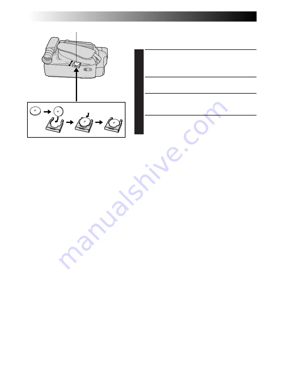
Clock (Lithium) Battery Insertion/Removal

This battery is necessary for clock operation and to
perform date/time settings.

1

SWITCH OFF POWER

Switch off the unit’s power and remove the power
supply unit (battery pack, AC Power Adapter/Battery
Charger, etc.).

2

REMOVE BATTERY HOLDER

Pull out the battery holder.

3

INSERT BATTERY IN HOLDER

Insert the battery in the holder, and be sure to have
the “+” mark visible.

4

RE-INSERT HOLDER

Slide the holder back into the slot until you hear a
click.

NOTES:

See “SAFETY PRECAUTIONS” (

Z

 pg. 2) for information

on safe handling of lithium batteries.

To avoid losing the battery and/or battery holder, place
the camcorder with the grip side up as shown in the
illustration when inserting/removing the battery.

Slot

Battery holder

Summary of Contents for GR-FXM75

Page 1: ...COMPACT VHS CAMCORDER LYT0361 001A INSTRUCTIONS ENGLISH EN GR FXM75 ...

Page 2: ... not using the AC Power Adapter Charger for a long period of time it is recom mended that you disconnect the power cord from AC outlet NOTES The rating plate serial number plate and safety caution are on the bottom and or the back of the main unit The rating plate serial number plate of the AC Power Adapter Charger is on its bottom This camcorder is designed to be used with PAL type colour televis...

Page 3: ...s designed exclusively for the VHS C video cassette Only cassettes marked VHS C can be used with this unit n HQ VHS is compatible with existing VHS equipment Digital Hyper Zoom Z pg 24 Picture Stabilizer Z pg 25 Integrated Auto Light Z pg 26 LCD Colour Monitor Z pg 16 Zoom in Zoom out Menu Adjustment Z pg 32 33 34 Digital Still Camera Built in PC communication capable Z pg 18 21 48 55 ...

Page 4: ... Shoulder Strap Attachment 13 Tripod Mounting 13 VIDEO RECORDING 14 17 Basic Recording 14 DIGITAL STILL CAMERA D S C SHOOTING 18 21 Basic Shooting 18 RECORDING 22 41 Basic Features 22 Advanced Features 27 VIDEO PLAYBACK 42 45 Basic Playback 42 Features 43 Using The Cassette Adapter 45 PLAYBACK 46 47 Basic Connections And Tape Dubbing 46 D S C PLAYBACK 48 55 Basic Playback 48 Connection 49 Advanced...

Page 5: ...nectors And Indicators 68 Indications 70 CAUTIONS 72 74 SPECIFICATIONS 75 OPTIONAL ACCESSORIES 75 PROVIDED ACCESSORIES AC Power Adapter Charger AA V15EK Cassette Adapter C P7U Battery Pack BN V12U Shoulder Strap Remote Control Unit RM V709U PC Connection Cable x 1 CD ROM including two software programmes Lithium Battery CR2025 x 2 for clock operation and remote control unit for Windows Audio Video...

Page 6: ...er Charger features a REFRESH function that allows you to fully discharge the battery pack before recharg ing Perform the REFRESH function after no less than 5 chargings To discharge the battery attach the battery pack to the adapter as shown in the above illustration Then push REFRESH The REFRESH indicator lights when discharging starts and goes out when discharging is complete CHARGE indicator M...

Page 7: ...p recharging or discharging part way through make sure to remove the battery pack before unplugging the adapter s AC cord Remove the battery pack from the adapter immediately after discharging To avoid interference with reception do not use the AC Power Adapter Charger near a radio Make sure you unplug the DC cord before charging or discharging the battery pack The CHARGE indicator may not light p...

Page 8: ... BATTERY HOLDER Pull out the battery holder 3 INSERT BATTERY IN HOLDER Insert the battery in the holder and be sure to have the mark visible 4 RE INSERT HOLDER Slide the holder back into the slot until you hear a click NOTES See SAFETY PRECAUTIONS Z pg 2 for information on safe handling of lithium batteries To avoid losing the battery and or battery holder place the camcorder with the grip side up...

Page 9: ...en press it When the setting begins blinking rotate the Select Dial until the correct setting appears and then press it The setting stops blinking Repeat this procedure until you re satisfied with the Date settings YEAR MONTH and DAY 5 SET TIME Rotate the Select Dial to move the highlight bar to TIME and then press it When the hour setting begins blinking rotate the Select Dial until the correct s...

Page 10: ...highlight bar to the correct setting T30 30 minutes of recording time T45 45 minutes and T60 60 minutes If you decide you want to return the tape length to the previous setting rotate the Select Dial to move the highlight bar to EXIT 4 CLOSE MENU SCREEN Press the Select Dial The Menu Screen reappears with the highlight bar on RETURN Press the Select Dial again to close the Menu Screen NOTE The tap...

Page 11: ...assette holder is still open may cause damage to the LCD monitor The cassette holder can t be opened unless a power supply is attached Make sure that the tape is not slack when loading the cassette If there is any slack turn the gear on the cassette in the direction of the arrow to take up the slack Make sure the Erase Protection tab is in the position that allows recording If not slide the tab So...

Page 12: ...p Button and Power Zoom Lever Refasten the Velcro strip Power Zoom Lever Recording Start Stop Button Set POWER to CAMERA AUTO or PRO GETTING STARTED cont Viewfinder Adjustment 1 SELECT OPERATION MODE Set the Power Switch to CAMERA AUTO or PRO 2 POSITION VIEWFINDER Adjust the viewfinder manually for best viewability see illustration on left 3 ADJUST DIOPTRE Turn the Dioptre Adjustment Control until...

Page 13: ...t left thread the strap through the top of the eyelet 1 then fold it back and thread it through the buckle 2 Repeat the procedure to attach the other end of the strap to the other eyelet 3 making sure the strap is not twisted 2 ADJUST LENGTH Adjust as shown in the illustration at left 4 2 3 1 4 Tripod Mounting 1 ALIGN AND TIGHTEN Align the screw and camera direction stud on the tripod with the cam...

Page 14: ...to CAMERA AUTO or PRO The power lamp lights and the camcorder enters the Record Standby mode The scene you are aimed at appears on the viewfinder screen with the word PAUSE superimposed upon it 3 START SHOOTING Press the Recording Start Stop Button appears in the viewfinder while recording is in progress Power lamp Tally lamp lights while recording is in progress Power Switch Position According to...

Page 15: ...s power shuts off automatically Set the Power Switch to POWER OFF and then back to CAMERA to turn the camcorder on again If the Recording Start Stop button is pressed after the Record Standby mode has continued for over 5 minutes recording may not start immediately If you are recording on a cassette from the middle such as when a tape is removed and re inserted during recording use the Retake func...

Page 16: ... Tilt the LCD monitor upward downward for best viewability Z pg 17 and press the Recording Start Stop Button appears in the LCD monitor while recording is in progress 4 STOP RECORDING Press the Recording Start Stop Button again to stop recording The camcorder re enters the Record Standby mode NOTES When you use the LCD monitor outdoors in direct sunlight the LCD monitor may be difficult to see If ...

Page 17: ...nterface Shooting The person you shoot can view himself herself in the LCD monitor and you can even shoot yourself while viewing your own image in the LCD monitor 1 TILT LCD MONITOR UPWARD Open the LCD monitor and tilt it upward to 180 degrees so that it faces forward When the LCD monitor is tilted upward to an angle of over approx 105 degrees the monitor image is inverted vertically and the viewf...

Page 18: ... an image appears 2 SELECT PICTURE MODE Do steps 2 and 3 of OPERATION on pg 20 Set PICTURE to FINE or STANDARD in the Menu Screen as required There are two modes FINE allows you to shoot up to approx 30 still images with higher resolution and STANDARD allows you to shoot up to approx 60 still images with lower resolution 3 SELECT SNAPSHOT MODE Rotate the Select Dial to move the highlight bar to SN...

Page 19: ...n the WIDE mode Z pg 33 the Snapshot image is recorded without the black bars at the top and bottom of the screen Pictrue mode display Remaining number of shots Blinking FULL Snapshot mode with no frame M DRIVE u Motor Drive mode PIN UP Pin Up mode MULTI 4 Multi Analyzer 4 MULTI 9 Multi Analyzer 9 There is a momentary camera shutter type blackout together with the image Continuous camera shutter t...

Page 20: ...re suitable for post production on a PC STANDARD allows you to shoot up to approx 60 still images in a format based on JPEG Joint Photographic Experts Group Since in this mode twice as many still images can be shot as in the FINE mode select this mode when you wish to shoot many still images OPERATION 1 Turn the LENS COVER Open Close Ring to open the lens cover and set the System Select Switch to ...

Page 21: ... this happens we recommend that you use the viewfinder When the remaining number indicator displays 0 blinking it is not possible to continue storing pictures until you delete some shots to make room for new ones Perform DELETE function in the Menu Screen to remove pictures you do not need Zpg 54 The Picture Mode can be switched to either FINE or STANDARD Since the remaining number of shots availa...

Page 22: ...CTION 1 SELECT OPERATION SYSTEM AND MODE Turn the LENS COVER Open Close Ring to open the lens cover and set the System Select Switch to VIDEO Set the Power Switch to PRO The power lamp lights and the camcorder enters Record Standby mode 2 SELECT SNAPSHOT MODE Press MENU The Menu Screen appears Rotate the Select Dial to move the highlight bar to SNAPSHOT and press it SNAPSHOT Menu appears Rotate th...

Page 23: ...aining number indicator displays 0 blinking the still image will be recorded onto the tape but not in the built in memory If you wish to store a still image in the built in memory Z pg 54 The Picture Mode can be switched to either FINE or STANDARD Since the remaining number of shots available depends on the selected Picture Mode switching the Picture Mode will vary this number If SNAPSHOT is press...

Page 24: ...cker you push the Power Zoom Lever the quicker the zoom action NOTES Focusing may become unstable during Zooming In this case set the zoom while in Record Standby lock the focus by using the manual focus Z pg 37 then zoom in or out in Record mode The zoom level indicator 5 moves during zoom Once the zoom level indicator reaches the top of the zoom indicator bar all magnification from that point is...

Page 25: ...ures may become monochrome or darken during Retake This is normal FEATURE Picture Stabilizer PURPOSE To compensate for unstable images caused by camera shake particularly at high magnification OPERATION 1 Press P STABILIZER appears n To switch off the Picture Stabilizer press P STABILISER The indicator disappears NOTES Accurate stabilisation may not be possible if hand shake is excessive or under ...

Page 26: ...he camcorder senses insufficient lighting on the subject ON Always keeps the light on as long as the camcorder is turned on n The video light can only be used with the camcorder s power on n It is recommended to set the white balance Z pg 38 to when you use the video light n When not using the video light turn it off to save battery power NOTES Even if the battery indicator does not blink if the b...

Page 27: ... and the fade wipe standby mode is canceled Fade in Recording Start Stop Button After 2 sec EFFECT Button Ex Fader Display Fade out Power Switch System Select Switch RECORDING Advanced Features OFF No indication FADER Fades in out to a black screen MOSAIC Fader Gradually turns returns the picture into from a mosaic pattern SHUTTER Wipe A black screen moves in from the top and bottom closing over t...

Page 28: ...mode s name and its indication are displayed for approx 2 seconds Then the name disappears and only the indication remains The mode is activated NOTES Only one mode can be engaged at a time The screen becomes slightly reddish when the Fade Wipe Z pg 27 is used in the Sepia mode The screen becomes slightly dark in the High Speed Shutter mode Use in well lit situations In the High Speed Shutter or S...

Page 29: ...g Filter Makes the picture look misty white as when an external fog filter is attached to the lens Softens the image and gives it a fantasy look Display Mode Twilight TWILIGHT Twilight Dusk twilight scenery fireworks etc look more natural and dramatic The following happens when Twilight mode is selected Auto gain control is turned off White Balance is set to FINE day mode but can also be manually ...

Page 30: ...E TIME DISP Menu 4 SELECT THE DESIRED MODE Move the highlight bar to the desired mode by rotating the Select Dial then press it The desired mode is activated You should have already performed the Date Time Setting procedure Z pg 9 If you haven t do so first 5 CLOSE MENU SCREEN The Menu Screen reappears with the highlight bar on RETURN Then press the Select Dial to close the Menu Screen NOTES DISPL...

Page 31: ...Switch to PRO 2 ACCESS MENU SCREEN Press the Select Dial to display the Menu Screen 3 ACCESS TITLE MENU Move the highlight bar to TITLE by rotating the Select Dial while in Record Standby Then press it to display the TITLE Menu 4 SELECT THE DESIRED MODE Move the highlight bar to the desired mode by rotating the Select Dial then press it The desired mode is activated If you wish to make the title i...

Page 32: ... Menu Screen 1 from Menu Screen 2 rotate the Select Dial to BACK and press it If the setting you want cannot be found in the Menu Screen place the highlight bar on RETURN then go to step 6 4 MAKE SETTING Press the Select Dial The setting procedure depends on the function you select If you select FOCUS EXPOSURE TITLE DATE TIME DISP DATE TIME PICTURE or SNAP SHOT see respective pages FOCUS Z pg 36 3...

Page 33: ...ed although the highlight bar will move on the Menu Screen like the setting procedure Functions listed without an asterisk are available with the System Select Switch set to either D S C or VIDEO Menu Screen Available Using The Select Dial FOCUS EXPOSURE WIDE S LX CONTINUED ON NEXT PAGE Factory preset Menu Screen Available Using The MENU Button This Menu Screen cannot be accessed while recording M...

Page 34: ... current date and time Z pg 9 Allows you to set the tape length depending on the tape used Z pg 10 Allows you to select the image setting FINE or STD when storing in the camcorder s memory Z pg 20 Displayed with the System Select Switch set to either VIDEO Z pg 22 or D S C Z pg 19 Displayed only with the System Select Switch set to D S C Z pg 19 This feature allows you to set the parameters for An...

Page 35: ...osure control level counter appears 5 ADJUST EXPOSURE To brighten the image rotate the Select Dial upward The exposure control level counter increases maximum 06 Go to step 6 To darken the image rotate the Select Dial downward The exposure control level counter decreases maximum 06 Go to step 6 6 END ADJUSTMENT OF EXPOSURE Press the Select Dial The Menu Screen reappears with the highlight bar on R...

Page 36: ...ntical patterns that are regularly repeated When the scene is affected by sunbeams or light reflecting off the surface of a body of water When shooting a scene with a high contrast background The low contrast warning appears NOTES If the lens is smeared or blurred accurate focusing is not possible Keep the lens clean wiping with a piece of soft cloth if it gets dirty When condensation occurs wipe ...

Page 37: ...upward appears and blinks Go to step 6 To nearer subject rotate the Select Dial downward appears and blinks Go to step 6 6 END ADJUSTMENT OF FOCUS Press the Select Dial The Menu Screen reappears with the highlight bar on RETURN 7 CLOSE MENU SCREEN Press the Select Dial The Menu Screen disppears and reappears to indicate the focus is locked NOTES To return to Auto Focus select AUTO in step 4 To re ...

Page 38: ... W B by rotating the Select Dial then press it The Menu Screen disap pears and the M W B Menu appears 4 SET FUNCTION PARAMETERS Move the highlight bar to the required white balance by rotating the Select Dial AUTO The white balance is adjusted automatically This is the factory preset position FINE When shooting outdoors on a sunny day CLOUD When shooting outdoors on a cloudy day HALOGEN When using...

Page 39: ...E MENU SCREEN Press the Select Dial again to close the Menu Screen To Change The Tint For Recording in step 2 substitute coloured paper for white The white balance is adjusted based on the colour changing the tint Red paper deeper green blue paper orange yellow paper deeper purple NOTES In step 2 it may be difficult to focus on the white paper in some circumstances In such a case adjust focus manu...

Page 40: ...N Press MENU 2 ACCESS INT TIME MENU Rotate the Select Dial to move the highlight bar to NEXT in Menu Screen 1 and press it to display Menu Screen 2 Then move the highlight bar to INT TIME and press it 3 SET INTERVAL TIME Rotate the Select Dial to move the highlight bar to the desired time then press it The Menu Screen reappears with the highlight bar on RETURN 4 CLOSE MENU SCREEN Press the Select ...

Page 41: ...recording make sure the Animation or Time Lapse mode is deactivated Self Timer Animation and Time Lapse are canceled when the power is shut off or when the cassette is ejected Time Lapse You can record sequentially at preset time spans Leaving the camcorder aimed at a specific subject you can record subtle changes over an extended period of time NOTE Before performing the following steps make sure...

Page 42: ...rn on again set the Power Switch to POWER OFF then to PLAY When the Power Switch is set to PLAY and the LCD monitor is opened at an angle of 60 degrees or more the LCD monitor switches on and the viewfinder switches off automatically to save power The playback picture can also be viewed in the viewfinder with the LCD monitor shut or on a connected TV Z pg 46 47 Camcorder operation is the same as d...

Page 43: ... eliminate noise bars that appear on screen during playback Initial setting is Auto Tracking Manual Tracking is also available 1 ACTIVATE MANUAL TRACKING Press P AE and EFFECT simultaneously Then press P AE or EFFECT as many times as necessary until the noise bars disappear To return to Auto Tracking press P AE and EFFECT simultaneously AT blinks When Auto Tracking finishes the indication disappea...

Page 44: ...nce you release it normal playback resumes Noise bars appear and pictures may become monochrome or darken during Shuttle Search This is normal FEATURE Counter Memory Function PURPOSE To make it easier to locate a specific tape segment OPERATION 1 Press COUNTER R M and hold for more than 1 second The counter resets to 0 00 00 2 Press COUNTER R M for less than 1 second M appears 3 After recording or...

Page 45: ...R and play the tape back as you would any other 4 REMOVE CASSETTE FROM ADAPTER Slide the latch and the compartment door opens automatically This may take around 10 seconds Do not attempt to force the adapter open Then insert your finger in the hole on the underside of the adapter as shown in the illustration at left and push up and remove the cassette NOTES During tape loading and unloading do not...

Page 46: ...ions Use the provided Video and Audio cables Connection For Tape Dubbing When connecting the cables open this cover Video cable provided To VIDEO IN Audio cable provided To Video Output To Audio Output TV VCR Connector cover To TV or VCR To AUDIO IN Power Switch PLAY PAUSE 4 6 Button Connector cover Audio cable provided To Video Output Video cable provided To VIDEO IN VCR Recording deck TV To AUDI...

Page 47: ...ecially shielded do not place the speakers adjacent to the TV as interference will occur in the camcorder playback picture Tape Dubbing 1 CONNECT EQUIPMENT Following the illustration on pg 46 connect the camcorder and the VCR 2 PREPARE FOR DUBBING Set the camcorder s Power Switch to PLAY turn on the VCR s power and insert the appropriate cassettes in the camcorder and the VCR 3 SELECT VCR MODE Eng...

Page 48: ...ge goes next Even if you shoot a new picture after playing back a still image with a low number this will not overwrite the existing picture because new pictures are automatically stored after the still image most recently stored in memory NOTES When the Power Switch is set to PLAY and the LCD monitor is opened at an angle of 60 degrees or more the LCD monitor switches on and the viewfinder switch...

Page 49: ...igator The image data transferred to a Windows PC can also be further processed using Mr Photo Gold and the still image processed on the PC can be inserted onto a tape Z pg 63 To assure safety make sure all units are turned off before making any connection 1 CONNECT TO PERSONAL COMPUTER Connect the camcorder s DIGITAL connector to the COM Port RS 232C on a Windows PC using the provided PC connecti...

Page 50: ...u Screen appears 3 SELECT FUNCTION Rotate the Select Dial to place the highlight bar on the desired function If the setting you want cannot be found in the Menu Screen place the highlight bar on RETURN then press the Select Dial 4 MAKE SETTING Press the Select Dial The setting menu of the selected function appears The setting procedure depends on the function you select If you select SLIDE SHOW 1 ...

Page 51: ...l twice Lets you protect selected still images from accidental erasure Select a still image for which you want to perform Protect to put a padlock mark next to it A still image with a padlock mark cannot be deleted When selecting a still image to protect you can check six still images stored in memory at a time Z pg 53 Allows you to delete some still images already stored in memory Z pg 54 CAUTION...

Page 52: ...he whole screen then the screen enters normal playback On the INDEX Menu 6 still images are displayed at a time When viewing the still images that follow the 6th one rotate the Select Dial to move the frame from Index No 1 to No 6 and then rotate it further downward The frame is placed on the 7th still image automatically Images after the 7th one can also be accessed in the same way If the desired...

Page 53: ...he Select Dial to move the frame from Index No 1 to No 6 then rotate it further downward The frame is placed automatically on the 7th still image Images after the 7th one can also be accessed in the same way To complete Protect go to step 5 5 CLOSE MENU SCREEN Rotate the Select Dial upward to place the highlight bar on EXIT then press it twice To remove Protect perform steps 1 through 3 rotate the...

Page 54: ...go to step 5 To delete all the still images stored in memory at once without checking them select ALL then go to step 6 To quit the Delete Mode rotate the Select Dial to place the highlight bar on EXIT then press it twice 5 SELECT ON DELETE SELECT MENU Rotate the Select Dial to move the frame to the desired still image then press it appears above the selected still image When you have finished sel...

Page 55: ...m Protect for the necessary ones Z pg 53 or save them on a PC so that you do not lose them accidentally Z pg 49 Even if ALL is selected on the DELETE Menu it is not possible to delete a still image with a padlock mark ALL only deletes all still images that are not protected After images are deleted from memory the remaining images are automatically moved up to fill in any gaps in the numerical seq...

Page 56: ...ithium batteries Z pg 2 The Full Function Remote Control Unit can operate this camcorder from a distance as well as the basic operations Playback Stop Pause Fast Forward and Rewind of your VCR The RM V709U remote control unit makes additional recording functions possible Lock hole Functions With the camcorder s Power Switch set to CAMERA AUTO or PRO Transmits the beam signal Self Timer Time Lapse ...

Page 57: ...rol until the Rec Time indicator disappears Time Lapse 1 Set Instead of performing steps 1 through 3 on pg 41 Time Lapse press INT TIME and REC TIME on the remote control Each time INT TIME is pressed the Interval Timer indicator appears changing in the following order 15S 30S 1MIN 5MIN and No indication off Each time REC TIME is pressed the Rec Time indicator appears changing in the following ord...

Page 58: ...R and point the remote towards the VCR s infrared sensor Then referring to the VCR CODE LIST on the left press and hold MBR SET and press button A and then B The code is automatically set once you release MBR SET and the VCR s power comes on 2 OPERATE VCR Make sure the VCR s power is on Then while holding VCR CTL press the button on the remote for the desired function The functions the remote can ...

Page 59: ...he RM V709U s PAUSE IN connector 2 PREPARE CAMCORDER Insert a recorded tape Set the System Select Switch to VIDEO and set the Power Switch to PLAY 3 PREPARE VCR Turn the power on insert a recordable tape and engage the AUX mode refer to the VCR s instructions CONTINUED ON NEXT PAGE Open the cover To Audio Output To Remote PAUSE To J terminal JLIP RM V709U provided VCR TV Audio cable provided To PA...

Page 60: ... the screen 7 REGISTER ADDITIONAL SCENES Repeat steps 5 and 6 for each additional scene as many as 8 8 MAKE CORRECTIONS IF NECESSARY Press CANCEL during steps 5 and 6 to erase the most recently registered point NOTES There must be at least one second between an in point and its corresponding out point To ensure correct operation there should be at least 15 seconds between an out point and the next...

Page 61: ...There may be noise at in or out points on the edited tape with certain VCRs Edited tape VCR RM V709U provided Original tape camcorder Recording Start Stop Button PAUSE 6 Button STOP 5 Button Power Switch REW 2 Button Remote Sensor VCR REC STBY ON OFF Using the RM V709U it is also possible to perform deck to deck Random Assemble Editing The playback deck must be an R A Edit capable JVC VCR The reco...

Page 62: ...recorded tape and press PAUSE exactly at the point where the new scene should start 5 ENGAGE INSERT EDITING MODE Press and hold INSERT and without releasing INSERT press and release PAUSE The Insert Editing mode is engaged When the scene the camcorder is aimed at appears on the screen go to the next step 6 BEGIN INSERT EDITING Press START STOP When the counter reaches 0 00 00 editing stops automat...

Page 63: ...automatically and the camcorder enters the Insert Pause mode To insert still images in sequential order onto the tape press REW 2 PAGE or FF 3 PAGE to move the page forward To insert still images at random onto the tape first record the still image you selected in step 1 onto the tape then press START STOP to engage the Insert Pause mode To select another still image press REW 2 PAGE or FF 3 PAGE ...

Page 64: ... Standby or the edit points will not be accurate If the microphone is too close to the TV or if the TV s volume is too high whistling or howling may occur NOTES for Insert Editing and Audio Dubbing Insert Editing and Audio Dubbing may not work correctly if the tape contains blank segments or if the recording speed was changed during the original recording To edit dub onto a tape make sure the Eras...

Page 65: ...try turning the power back on If it still doesn t come on consult your nearest JVC dealer The Power Switch is set to AUTO Certain combinations of modes or effects are not possible to use Press DISPLAY for longer than 1 second to make the indica tions appear Z pg 15 This sometimes occurs when the contrast between the back ground and the object is great It is not a defect of the camcorder Sunlight i...

Page 66: ... a tape set the camcorder to the Recording mode for about 5 seconds so that the tape runs smoothly Using the Fade in function at this point is a good way to begin an animated program Z pg 41 57 The TV has not been set to its VIDEO mode or channel If A V connection is used the TV s VIDEO TV Switch has not been set to VIDEO If the System Select Switch is set to D S C it is not possible to play back ...

Page 67: ...set REC TIME in the Menu Screen PLAYBACK OTHER When the System Select Switch is set to D S C Since the camcorder is a microcomputer controlled device external noise and interference from a TV a radio etc might prevent it from functioning properly For example when a still image you shot is stored in the camcorder s built in memory the above may cause the following Although the remaining number of s...

Page 68: ...68EN INDEX Controls Connectors And Indicators O P 1 p Q w o u r e 2 W E R 3 4 5 6 i T Y I U t y 7 8 9 0 q ...

Page 69: ... 14 Power Switch Z pg 14 18 42 48 Battery Release Switch BATTERY RELEASE Z pg 6 q PUSH Button Z pg 11 Connectors w DC IN Jack Z pg 7 The connectors e to y are located beneath the cover e Video Output Connector Z pg 46 r Audio Output Connector Z pg 46 t J Terminal JLIP Joint Level Interface Protocol Connector Connect the editing cable when performing Random Assemble Editing Z 58 61 It is used to co...

Page 70: ...70EN INDEX Indications NORM S INDEX 20X 30MIN T45 15S 5S BRIGHT 25 12 99 22 50 00 MERRY CHRISTMAS LENS COVER TAPE END PAUSE FADER 2 REC 01 FINE 12 SP 1X 7 8 9 0 q 6 5 3 4 1 a b 2 ...

Page 71: ...ay Z pg 31 Date Time Display Z pg 30 Bright Level Indicator Z pg 43 Speaker Volume Indicator Z pg 43 Battery Pack Remaining Power Indicator Changes as follows according to the battery pack s remaining power level When the power is almost gone the indicator blinks battery power warning then the unit shuts off Replace the battery pack with a fully charged one Note The symbol containing 3 darkened sq...

Page 72: ...Storage 10 C to 30 C Recharging time is based on room temperature of 20 C The lower the temperature the longer recharging takes CAUTIONS DANGER Video Light The video light becomes extremely hot Do not touch it either while in operation or soon after turning it off otherwise serious injury may result Do not place the camcorder into the carrying case immediately after using the video light since it ...

Page 73: ...llow inflammables water or metallic objects to enter the unit remove the battery pack or disconnect the power supply while the power is on leave the battery pack attached when the camcorder is not in use 2 Avoid using the unit in places subject to excessive humidity or dust in places subject to soot or steam such as near a cooking stove in places subject to excessive shock or vibration near a tele...

Page 74: ...rcular motion Do not use conventional disc cleaners or cleaning spray Do not bend the CD ROM or touch its mirror surface Do not store your CD ROM in a dusty hot or humid environment Keep it away from direct sunlight CAUTIONS cont For Your Maintenance 1 After Use 1 Set the Power Switch to POWER OFF to turn off the camcorder 2 Open the LCD monitor to an angle of over 60 degrees Slide EJECT to open t...

Page 75: ...attery x 1 Image size 640 x 480 pixels when captured on a PC Operating temperature 0 C to 40 C Operating humidity 35 to 80 Storage temperature 20 C to 50 C Weight Approx 890 g Dimensions 99 W x 119 H x 198 D mm with the LCD monitor closed and with the viewfinder fully tilted downward Pickup 1 4 format CCD Lens F1 6 f 3 9 to 62 4 mm 16 1 power zoom lens with auto iris and macro control filter diame...

Page 76: ...GR FXM75 SH Printed in Japan 0299FOV UN SN EN VICTOR COMPANY OF JAPAN LIMITED Registered Trademark owned by VICTOR COMPANY OF JAPAN LTD COPYRIGHT 1999 VICTOR COMPANY OF JAPAN LTD ...

Reviews: