background image

EDITING

36 

EN

MasterPage: Left

It is also possible to copy recorded scenes from the 
camcorder onto another video unit equipped with a DV 
connector. Since a digital signal is sent, there is little if 
any image or sound deterioration. 

To use this camcorder as a player

1

Make sure all units are turned off.

2

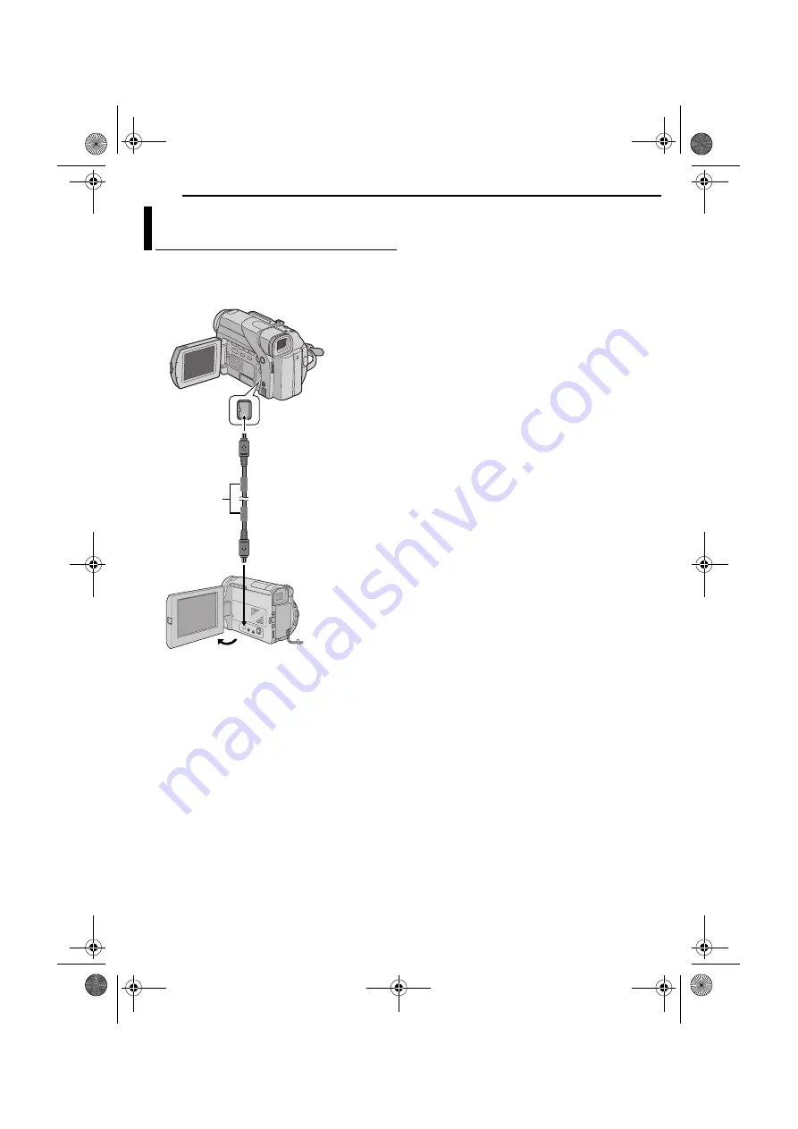
Connect this camcorder to a video unit equipped with 

a DV input connector using a DV cable as shown in the 
illustration.

3

Set this camcorder’s 

VIDEO/MEMORY

 Switch to 

“VIDEO”.

4

Set this camcorder’s Power Switch to “PLAY” while 

pressing down the Lock Button located on the switch.

5

Turn on the video unit’s power.

6

Insert the source cassette in this camcorder.

7

Insert the recording cassette in the video unit.

8

Press 

4

/

9

 on this camcorder to start playback of the 

source cassette.

9

At the point you want to start dubbing, engage the 

video unit’s Record mode.

10

To pause dubbing, engage the video unit’s Record-

Pause mode and press 

4

/

9

 on this camcorder.

11

Repeat step

8

10

 for additional editing. Stop the 

video unit and camcorder.

NOTES:

It is recommended to use the AC Adapter as the power 
supply instead of the battery pack. (

pg. 7)

If the remote control is used when both the player and 
recorder are JVC video units, both units will perform the 
same operation. To prevent this from happening, press the 
buttons on both units.

If a blank portion or disturbed image is played back on the 
player during dubbing, the dubbing may stop so that an 
unusual image is not dubbed.

Even though the DV cable is connected correctly, 
sometimes the image may not appear in step 

9

. If this 

occurs, turn off the power and make connections again.

If “Playback Zoom” (

pg. 16) o“Playback Special Effects” 

(

pg. 16) is attempted or 

SNAPSHOT

 is pressed during 

playback, only the original playback image recorded on the 
tape is output from the DV connector.

When using a DV cable, be sure to use the optional 
JVC VC-VDV204U DV cable. 

Dubbing To A Video Unit Equipped With A 
DV Connector (Digital Dubbing) 

Core filter

To DV OUT

DV cable 
(optional)

Video unit equipped 
with DV connector

To DV IN

GR-D63EK.book  Page 36  Tuesday, December 16, 2003  7:44 PM

Summary of Contents for GR-D63

Page 1: ...RECORDING PLAYBACK 11 DIGITAL STILL CAMERA D S C RECORDING PLAYBACK 18 ADVANCED FEATURES 24 REFERENCES 39 TERMS 54 To deactivate the demonstration set DEMO MODE to OFF 墌 pg 24 26 DIGITAL VIDEO CAMERA Dear Customer Thank you for purchasing this digital video camera Before use please read the safety information and precautions contained in the pages 2 3 to ensure safe use of this product GR D63EK_01...

Page 2: ...fety caution are on the bottom and or the back of the main unit The rating information and safty caution of the AC Adapter are on its upper and lower sides Caution on Replaceable lithium battery The battery used in this device may present a fire or chemical burn hazard if mistreated Do not recharge disassemble heat above 100 C or incinerate Replace battery with Panasonic Matsushita Electric Sanyo ...

Page 3: ...s so that you are distracted from the requirements of road safety It is illegal to watch television whilst driving DON T listen to headphones at high volume as such use can permanently damage your hearing DON T obstruct the ventilation of the equipment for example with curtains or soft furnishings Overheating will cause damage and shorten the life of the equipment DON T use makeshift stands and NE...

Page 4: ... ADDITIONAL FEATURES FOR D S C 20 Viewing File Information 20 Removing On Screen Display 20 Protecting Files 20 Deleting Files 21 Dubbing Still Images Recorded On A Tape To A Memory Card 21 Setting Print Information DPOF Setting 22 Resetting The File Name 23 Initialising A Memory Card 23 ADVANCED FEATURES 24 MENUS FOR DETAILED ADJUSTMENT 24 Changing The Menu Settings 24 Recording Menus 25 Playback...

Page 5: ...f the camcorder provided cables may be equipped with one or more core filter If a cable has only one core filter the end that is closest to the filter should be connected to the camcorder Make sure to use the provided cables for connections Do not use any other cables How To Attach The Lens Cap To protect the lens attach the provided lens cap to the camcorder as shown in the illustration NOTE To c...

Page 6: ...against the battery pack mount a 2 Slide up the battery pack until it locks in place b 3 Set the Power Switch to OFF CHARGE 4 Connect the AC Adapter to the camcorder then connect the Power Cord to the AC Adapter 5 Plug the AC Adapter into an AC outlet The POWER CHARGE lamp on the camcorder blinks to indicate charging has started 6 When the POWER CHARGE lamp goes out charging is finished Unplug the...

Page 7: ...erminals of the AC Adapter to come in contact with metals as this can result in a short circuit and cause malfunction For other notes 墌 pg 39 About Batteries DANGER Do not attempt to take the batteries apart or expose them to flame or excessive heat as it may cause a fire or explosion WARNING Do not allow the battery or its terminals to come in contact with metals as this can result in a short cir...

Page 8: ...ernal clock continues to operate Once you move the highlight bar to the first date time parameter day the clock stops When you finish setting the minute and press the MMENU VOL Wheel in the date and time begin operation from the date and time you have just set Operation Mode Power Switch Position A Full Auto Recording Allows you to record using NO special effects or manual adjustments Suitable for...

Page 9: ...to select BRIGHT and press it The Menu Screen closes and the brightness control indicator appears 6 Rotate the MMENU VOL Wheel until the appropriate brightness is reached 7 Press the MMENU VOL Wheel in It is also possible to adjust the brightness of the viewfinder by pulling out the viewfinder setting PRIORITY in the SYSTEM Menu to FINDER 墌 pg 24 26 and adjusting as described above To attach the c...

Page 10: ... 1 Make sure the camcorder s power is off 2 Open the LCD monitor 墌 pg 12 then open the card cover MEMORY CARD 3 To load a memory card firmly insert it with its clipped edge first To unload a memory card push it once After the memory card comes out of the camcorder pull it out Do not touch the terminal on the reverse side of the label 4 Close the card cover To protect valuable files available only ...

Page 11: ...OTES The image will not appear simultaneously on the LCD monitor and the viewfinder If the Record Standby mode continues for 5 minutes the camcorder s power shuts off automatically To turn the camcorder on again push back and pull out the viewfinder again or close and re open the LCD monitor LCD monitor viewfinder indications When power is supplied from a battery the battery indicator is displayed...

Page 12: ...e zoom in out effect or an instantaneous change in image magnification Zoom In Slide the Power Zoom Lever towards T Zoom Out Slide the Power Zoom Lever towards W The further you slide the Power Zoom Lever the quicker the zoom action NOTES Focusing may become unstable during Zooming In this case set the zoom while in Record Standby lock the focus by using the manual focus 墌 pg 32 then zoom in or ou...

Page 13: ...ape See the right column in the following cases When shooting again after playing back a recorded tape When power shuts off during shooting When a tape is removed and re inserted during shooting When shooting using a partially recorded tape When shooting on a blank portion located partway through the tape When shooting again after shooting a scene then opening closing the cassette holder cover Rec...

Page 14: ...his is not a malfunction ATTENTION During Shuttle Search parts of the picture may not be clearly visible particularly on the left side of the screen Blank Search Helps you find where you should start recording in the middle of a tape to avoid time code interruption 墌 pg 13 1 Load a cassette 墌 pg 10 2 Set the VIDEO MEMORY Switch to VIDEO 3 Set the Power Switch to PLAY while pressing down the Lock B...

Page 15: ... directly exposed to sunlight or powerful lighting Buttons And Functions A Infrared beam transmitting window The following buttons are available only when the camcorder s Power Switch is set to PLAY B AUDIO Button 墌 pg 24 28 C PAUSE Button 墌 pg 16 Up Button 墌 pg 16 D SLOW Rewind Button 墌 pg 16 E REW Button 墌 pg 14 19 Left Button 墌 pg 16 F INSERT Button 墌 pg 38 G STOP Button 墌 pg 14 19 Down Button ...

Page 16: ...nt you want to zoom in press the Zoom Button T To zoom out press the Zoom Button W 3 You can move the image on the screen around to find a particular portion of the picture While holding down SHIFT press L Left F Right U Up and E Down To end zoom press and hold W until magnification returns to normal Or press STOP 8 and then press PLAY U during video playback NOTES Zoom can also be used during slo...

Page 17: ...UX input mode and set the TV to its VIDEO mode To choose whether or not the following displays appear on the connected TV Date Time Set DATE TIME to AUTO ON or OFF 墌 pg 24 28 Or press DISPLAY on the remote control to turn on off the date indication Time Code Set TIME CODE to ON or OFF 墌 pg 24 28 Indications other than date time and time code Set ON SCREEN to OFF LCD or LCD TV 墌 pg 24 28 NOTES It i...

Page 18: ...pg 21 When you do not want to hear the shutter sound set BEEP to OFF 墌 pg 24 26 A Image Size 墌 pg 27 52 B Shooting Icon 墌 pg 52 C Card Icon 墌 pg 52 D Picture Quality 墌 pg 27 52 E Remaining Number Of Shots 墌 pg 52 Approximate Number of Storable Images Optional Provided Basic Shooting D S C Snapshot Power Switch Lock Button VIDEO MEMORY SNAPSHOT Monitor Opening Button Snapshot mode with no frame The...

Page 19: ...not compatible with DCF cannot be viewed with this camcorder UNSUPPORTED FILE will be displayed Playback Zoom Available only with the remote control provided 墌 pg 16 You can run through all the images stored in memory card automatically 1 Perform steps 1 3 in Normal Playback Of Images 2 Press 4 9 to start Auto Playback If you press 3 during Auto Playback files are displayed in descending order If ...

Page 20: ...3 or 5 to select the desired file 8 Rotate the MMENU VOL Wheel to select EXECUTE and press it To cancel protection select RETURN Repeat steps 7 and 8 for all files you want to protect To protect all files stored in the memory card 6 Rotate the MMENU VOL Wheel to select PROT ALL and press it The PROTECT screen appears 7 Rotate the MMENU VOL Wheel to select EXECUTE and press it To cancel protection ...

Page 21: ...S Protected files 墌 pg 20 cannot be deleted To delete them remove protection first Once files are deleted they cannot be restored Check files before deleting CAUTION Do not remove the memory card or perform any other operation such as turning off the camcorder during deletion Also be sure to use the provided AC Adapter as the memory card may be corrupted if the battery becomes exhausted during del...

Page 22: ...nt For Each 2 Rotate the MMENU VOL Wheel to select CURRENT and press it The DPOF screen appears 3 Press 3 or 5 to select the desired file 4 Rotate the MMENU VOL Wheel to select the number indication 00 and press it 5 Select the number of prints by rotating the MMENU VOL Wheel towards to increase number or towards to decrease the number and press it Repeat steps 3 through 5 for the desired number o...

Page 23: ...he numerical sequence If the file name reaches DVC09999 a new folder such as 101JVCGR will be made and the file name will start again from DVC00001 You can initialise a memory card anytime After initialising all files and data stored in the memory card including those which have been protected are cleared 1 Set the VIDEO MEMORY Switch to MEMORY 2 Set the Power Switch to PLAY while pressing down th...

Page 24: ...enus m CAMERA 墌 pg 25 q MANUAL 墌 pg 25 s SYSTEM 墌 pg 26 n CAMERA DISPLAY 墌 pg 27 o DSC 墌 pg 27 t VIDEO 墌 pg 28 n VIDEO DISPLAY 墌 pg 28 1 Rotate the MMENU VOL Wheel to select the desired function and press it The Sub Menu appears Example m CAMERA Menu 2 Rotate the MMENU VOL Wheel to select the desired parameter 3 Press the MMENU VOL Wheel in Selection is complete Repeat the procedure if you wish to...

Page 25: ...processing and magnifying images zooming is possible from 16X the optical zoom limit to a maximum of 700X digital magnification Available only when the VIDEO MEMORY Switch is set to VIDEO FULL Snapshot mode with no frame PIN UP Pin Up mode FRAME Snapshot mode with frame For details on the procedure refer to Snapshot For Video Recording 墌 pg 31 OFF Allows you to shoot dark scenes with no picture br...

Page 26: ...Y Factory preset OFF Turns off sounds when performing any operations It also deactivates the shutter sound effect however the shutter sound is recorded onto the tape during Snapshot for Video Recording 墌 pg 31 BEEP The beep sounds when the power is turned on or off and at the beginning and end of recording It also activates the shutter sound effect 墌 pg 18 31 MELODY Instead of a beep a melody soun...

Page 27: ... the connected TV Frame numbers are not displayed during recording 墌 pg 13 墌 pg 8 Date Time Settings DSC Factory preset FINE STANDARD The Picture Quality mode can be selected to best match your needs Two Picture Quality modes are available FINE and STANDARD in order of quality NOTE The number of storable images depends on the selected picture quality as well as the composition of the subjects in t...

Page 28: ... you to set the video recording mode SP or LP depending on your preference It is recommended you use REC MODE in VIDEO Menu when using this camcorder as a recorder during dubbing 墌 pg 35 36 NOTE REC MODE can be set when the Power Switch is set to PLAY or M OFF When the SNAPSHOT button is pressed during tape playback the playback image pauses and normal playback will resume after approximately 6 se...

Page 29: ... Makes dark subjects or areas even brighter than they would be under good natural lighting Although the recorded image is not grainy it may look as if it is strobing due to the slow shutter speed 1 Set the Power Switch to M while pressing down the Lock Button located on the switch 2 Open the LCD monitor fully 墌 pg 12 3 Press NIGHT so that the Night Scope indicator appears The shutter speed is auto...

Page 30: ...WIPE WINDOW The scene starts in the centre of a black screen and wipes in toward the corners or comes in from the corners gradually wiping out to the centre WIPE SLIDE Wipe in from right to left or wipe out from left to right WIPE DOOR Wipe in as the two halves of a black screen open to the left and right revealing the scene or wipe out and the black screen reappears from left and right to cover t...

Page 31: ...hen the VIDEO MEMORY Switch is set to VIDEO This feature lets you record still images that look like photographs onto a tape 1 Set the VIDEO MEMORY Switch to VIDEO 2 Set the Power Switch to M while pressing down the Lock Button located on the switch 3 Open the LCD monitor fully 墌 pg 12 4 Set SNAP MODE to the desired mode 墌 pg 24 25 5 Press SNAPSHOT There is the sound effect of a shutter closing Th...

Page 32: ...may automatically zoom out depending on the distance between the camcorder and the subject This will not occur when TELE MACRO is set to ON 墌 pg 26 NOTE If you are using the viewfinder you should already have performed Viewfinder Adjustment 墌 pg 9 1 Set the Power Switch to M while pressing down the Lock Button located on the switch 2 Press FOCUS The manual focus indicator appears 3 To focus on a f...

Page 33: ... pupil of the human eye the iris contracts in well lit environments to keep too much light from entering and dilates in dim environments to allow in more light Use this function in the following situations When shooting a moving subject When the distance to the subject changes so its size in the LCD monitor or the viewfinder changes such as when the subject is backing away When shooting on a refle...

Page 34: ...nce Set u to AUTO 墌 pg 24 Or set the Power Switch to A NOTE White balance cannot be used when r is set to SEPIA or MONOTONE 墌 pg 31 Adjust the white balance manually when shooting under various types of lighting 1 Set the Power Switch to M while pressing down the Lock Button located on the switch 2 Open the LCD monitor fully 墌 pg 12 3 Set u to MWB 墌 pg 24 The indication blinks slowly 4 Hold a shee...

Page 35: ...Engage the VCR s AUX and Record Pause modes Refer to the instruction manual for the VCR 8 Press 4 9 on the camcorder to start playback of the source tape 9 At the point you want to start dubbing engage the VCR s Record mode 10 To pause dubbing engage the VCR s Record Pause mode and press 4 9 on the camcorder 11 Repeat steps 8 10 for additional editing Stop the VCR and camcorder NOTES It is recomme...

Page 36: ... 11 Repeat steps 8 10 for additional editing Stop the video unit and camcorder NOTES It is recommended to use the AC Adapter as the power supply instead of the battery pack 墌 pg 7 If the remote control is used when both the player and recorder are JVC video units both units will perform the same operation To prevent this from happening press the buttons on both units If a blank portion or disturbe...

Page 37: ...order When using a DV cable be sure to use the optional JVC VC VDV206U or VC VDV204U DV cable depending on the type of DV connector 4 or 6 pins on the PC If the PC connected to the camcorder via the USB cable is not powered the camcorder does not enter the USB mode The date time information cannot be captured into the PC Refer to the instruction manuals of the PC and Software The still images can ...

Page 38: ...eplacing a section of the original recording with minimal picture distortion at the in and outpoints The original audio remains unchanged Use the provided remote control NOTES Before performing the following steps make sure that TIME CODE is set to ON 墌 pg 24 28 Insert Editing is not possible on a tape recorded in the LP mode or on a blank portion of a tape To perform Insert Editing while watching...

Page 39: ...use the viewfinder instead The cassette holder cannot be opened unless a power supply is attached There may be a delay after you open the cassette holder cover until the cassette holder opens Do not use force Once the cassette holder is closed it recedes automatically Wait until it recedes completely before closing the cassette holder cover When the Recording Start Stop button is pressed it may ta...

Page 40: ...ted HSet ZOOM to 40X or 700X 墌 pg 25 The VIDEO MEMORY Switch is set to MEMORY HSet the VIDEO MEMORY Switch to VIDEO White spots or bright spots of light red green or blue may appear on the LCD monitor This may occur when the Night Scope function is activated during recording and is not a malfunction Video and D S C Playback The Power Switch is set to A or M HSet the Power Switch to PLAY 墌 pg 14 VI...

Page 41: ...墌 pg 24 25 Other problems The temperature of the battery is extremely high low Charging is difficult in places subject to extremely high low temperatures HTo protect the battery it is recommended to charge it in places with a temperature of 10 C to 35 C 墌 pg 45 The date time is not set HSet the date time 墌 pg 8 The built in clock battery has run out and the previously set date time has been erased...

Page 42: ...monitor s brightness setting is too dark HAdjust the brightness of the LCD monitor 墌 pg 9 HIf the monitor is tilted upward 180 degrees open the monitor fully 墌 pg 12 The speaker volume is too great HTurn the speaker volume down 墌 pg 14 HWipe them gently with soft cloth Wiping strongly can cause damage 墌 pg 48 To clean the viewfinder please consult your nearest JVC dealer TIME CODE is set to OFF HS...

Page 43: ... pg 8 Appears when the built in clock lithium battery is discharged and the previously set date time is erased 墌 pg 8 Appears for 5 seconds after power is turned on if the lens cap is attached Appears if Audio Dubbing is attempted on a blank portion of a tape 墌 pg 38 Appears if Audio Dubbing is attempted on a tape recorded in the LP mode 墌 pg 38 Appears if Audio Dubbing is attempted on a tape reco...

Page 44: ...ted Appears when playing back a file that is not compatible with DCF or a file with a size that is not compatible with this camcorder Appears when you attempt to shoot digital still images when the write protection tab on the SD Memory Card is set to the LOCK position The error indications E01 E02 or E06 show what type of malfunction has occurred When an error indication appears the camcorder turn...

Page 45: ...0 C to 40 C Storage 20 C to 50 C The lower the temperature the longer recharging takes Cassettes To properly use and store your cassettes be sure to read the following cautions During use make sure the cassette bears the Mini DV mark be aware that recording onto prerecorded tapes automatically erases the previously recorded video and audio signals make sure the cassette is positioned properly when...

Page 46: ... it to shock or excessive vibration during transportation keep the lens directed at extremely bright objects for long periods expose the lens and viewfinder s lens to direct sunlight carry it by holding the LCD monitor or the viewfinder swing it excessively when using the hand strap or the grip swing the soft camera case excessively when the camcorder is inside it Dirty heads can cause the followi...

Page 47: ...o the cool air from an air conditioner Moisture on the head drum can cause severe damage to the video tape and can lead to internal damage to the camcorder itself If malfunctioning occurs stop using the unit immediately and consult your local JVC dealer The camcorder is a microcomputer controlled device External noise and interference from a TV a radio etc might prevent it from functioning properl...

Page 48: ...t Then wipe again with a dry cloth 2 Press the Monitor Opening Button and open the LCD monitor Wipe gently with a soft cloth Be careful not to damage the monitor Close the LCD monitor 3 To clean the lens blow it with a blower brush then wipe gently with lens cleaning paper NOTES Avoid using strong cleaning agents such as benzine or alcohol Cleaning should be done only after the battery pack has be...

Page 49: ...rmat PAL standard Recording Playback format Video Digital component recording Audio PCM digital recording 32 kHz 4 channel 12 bit 48 kHz 2 channel 16 bit Cassette Mini DV cassette Tape speed SP 18 8 mm s LP 12 5 mm s Maximum recording time using 80 min cassette SP 80 min LP 120 min Storage media SD Memory Card MultiMediaCard Compression system Still image JPEG compatible File size Still image 2 mo...

Page 50: ...50 EN MasterPage Heading0_Left INDEX GR D63EK book Page 50 Tuesday December 16 2003 7 44 PM ...

Page 51: ... Opening Button 墌 pg 12 For models without button simply pull on bottom end of LCD monitor to open Connectors T S Video Output Connector S VIDEO 墌 pg 17 35 U USB Universal Serial Bus Connector 墌 pg 37 V Digital Video Connector DV i Link 墌 pg 36 37 W Audio Video Output Connector AV 墌 pg 17 35 X DC Input Connector DC 墌 pg 6 7 i Link refers to the IEEE1394 1995 industry specification and extensions t...

Page 52: ...e approximate remaining number of shots that can be stored during D S C recording The number increases or decreases depending on the Picture Quality Image Size etc During Both Video And D S C Recording a Operation Mode 墌 pg 8 b Night Scope Indicator 墌 pg 29 Appears when Night Scope is engaged Gain Up Mode 墌 pg 25 Appears when GAIN UP is set to AUTO and the shutter speed is automatically adjusted c...

Page 53: ...Indicator 墌 pg 43 g Date Time 墌 pg 27 28 h VOLUME Volume Level Indicator Speaker 墌 pg 14 The level indicator g moves BRIGHT Brightness Control Indicator LCD monitor Viewfinder 墌 pg 9 The level indicator g moves i Time Code 墌 pg 27 28 During D S C Playback a Operation Mode Indicator 墌 pg 20 b Folder File Number 墌 pg 20 c Battery Indicator 墌 pg 43 d Brightness Control Indicator LCD monitor Viewfinde...

Page 54: ...onitor Viewfinder 52 Initialising A Memory Card FORMAT 23 Insert Editing 38 Iris 33 Iris Lock 33 J Journalistic Shooting 13 L Loading A Cassette 10 Loading A Memory Card 10 M Manual Focus 32 Memory Card 10 45 Menu Screen CAMERA 25 CAMERA DISPLAY 27 D S C Playback 20 23 DSC 27 MANUAL 25 SYSTEM 26 28 VIDEO 28 VIDEO DISPLAY 28 Motor Drive Mode 31 MultiMediaCard 10 45 N Night Scope 29 P Picture Qualit...

Page 55: ...cifications 49 Still Playback 14 T Telephoto setting TELE MACRO 26 Time Code TIME CODE 13 27 Tripod Mounting 9 U Unloading A Cassette 10 Unloading A Memory Card 10 V VIDEO MEMORY Switch Position 8 Viewfinder Adjustment 9 W White Balance W BALANCE 34 White LED Light 29 Wide Mode WIDE MODE Cinema CINEMA 26 Squeeze SQUEEZE 26 Wipe In Out 30 Z Zooming ZOOM 12 25 GR D63EK book Page 55 Tuesday December ...

Page 56: ...COPYRIGHT 2003 VICTOR COMPANY OF JAPAN LTD EN GR D63 EK MasterPage BackCover Printed in Malaysia 1203 FO ID PJ GR D63EK_11Cover4 fm Page 56 Wednesday December 17 2003 12 37 PM ...

Reviews: