


(No.YF042)1-7
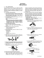
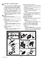
3.2.2 ASSEMBLY/DISASSEMBLY OF CABINET PARTS AND ELECTRICAL PARTS(1)
z
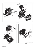
Disassembly procedure
Fig.3-2-1
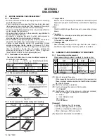
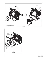
NOTE2:
For disassembly of the MONITOR ASSEMBLY, see "3.2.6
DISASSEMBLY of [12] MONITOR ASSEMBLY".
NOTE5a:
Another FPC overlaps the FPC of the VF ASSEMBLY. Be-
fore removing the FPC of the VF ASSEMBLY, remove
CN5a.
NOTE5b:
For disassembly of the VF ASSEMBLY, see "3.2.4 DISAS-
SEMBLY of [5] VF ASSEMBLY".
NOTE7:
In removing the LOWER ASSEMBLY, remove the SPAC-
ER, and remove the FPC.
Be careful not to damage the FPC.
NOTE8:
For disassembly of the OP BLOCK ASSEMBLY, see "3.2.5
DISASSEMBLY of [8] OP BLOCK ASSMBLY/CCD BOARD
ASSEMBLY ".
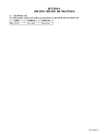
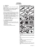
z
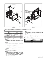
Destination of connectors
Fig.3-2-2
[1]
[2]
[3]
[4]
[5]
[6]
[7]
[8]
[9]
[10]
[11]
TOP COVER ASSEMBLY
UPPER CASE ASSEMBLY
(Inc. MONITOR ASSEMBLY)
REAR COVER ASSEMBLY
FRONT COVER ASSEMBLY
(Inc.MIC ASSEMBLY)
VF ASSEMBLY
BASE
LOWER ASSEMBLY
(Inc. FRONT BOARD ASSEMBLY/
SD BOARD ASSEMBLY)
OP BLOCK ASSEMBLY/
CCD BOARD ASSEMBLY
MAIN BOARD ASSEMBLY
MDA BOARD ASSEMBLY
MECHA ASSEMBLY
2(S1a),2(S1b),CN1
(S2a),(S2b),4(S2c),2(L2a),2(L2b)
CN2a,b
CN3,4(S3),4(L3)
(S4a),(S4b),JACK COVER(AV)ASSEMBLY
2(S4c),CN4
CN5a,b,2(S5),L5
2(S6)
CN7a,SPACER,CN7b,c,4
㧔
S7
㧕
2(S8),L8
CN9a,b,(S9a),2(S9b),CN9c
CN10a,b,c,d,2(S10)
(S11),SHIELD COVER(1),3(S11)
BKT(MECHA)ASSEMBLY
Fig.FA1
Fig.FA2
Fig.FA3
Fig.FA4
Fig.FA5
Fig.FA6
Fig.FA7
Fig.FA8
Fig.FA9
-
NOTE2
-
-
NOTE5a,b
-
NOTE7
NOTE8
-
-
-
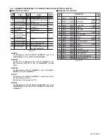
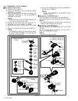
STEP
No.
PART
NOTE
Fig.
No.
POINT
CONNECTOR
PIN.
No
CONN.
No.
CN1
MAIN
CN109
ZOOM SW(OPE)
-
6
CN2a
MAIN
CN112
MONITOR
CN7601 39/20,
/CN7602 20
CN2b MAIN
CN110
JUNCTION
CN401 10
CN3 MAIN CN104 REAR
CN501 40
CN4 MAIN CN107 MIC
ASSY -
4
CN5a MAIN
CN105
SD
CN901 22
CN5b
MAIN
CN103
VF FPC ASSY
-
22
CN7a FRONT CN701
MAIN
CN108 24
CN7b MAIN
CN102
CCD
CN5201 20
CN7c
MAIN
CN101
OP BLOCK ASSY
-
24
CN9a MAIN
CN106
MDA
CN305 30
CN9b MAIN
CN113
HEAD
-
8
CN9c MAIN
CN114
SENSOR
-
16
CN10a MDA
CN301
CAPSTAN
MOTOR
-
18
CN10b MDA
CN302
DRUM
MOTOR
-
11
CN10c MDA
CN303
ROTARY
ENCODER
SW -
6
CN10d MDA
CN304
LOADING
MOTOR
-
6