background image

13

Menu Configuration

—MAIN MENU

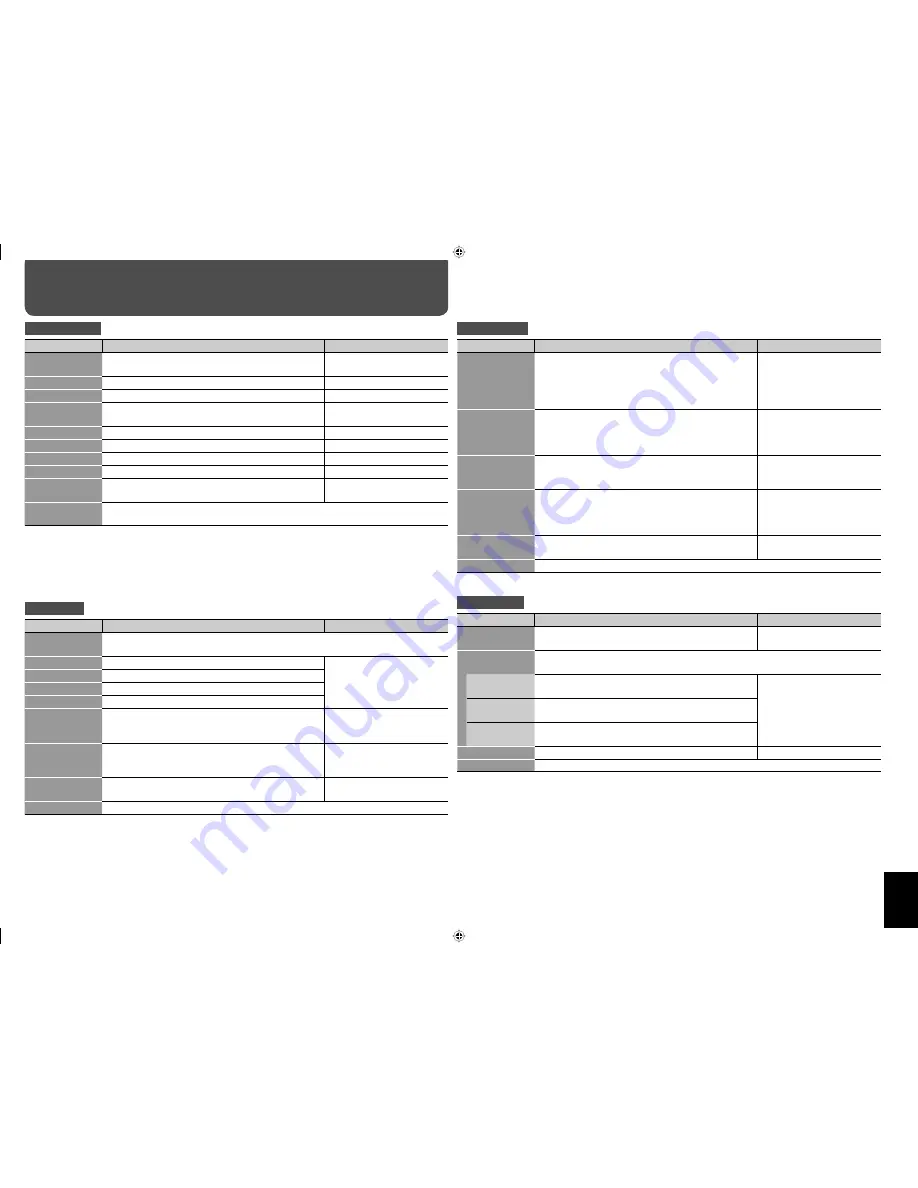
PICTURE SETTING

Item

To do

Setting value

PICTURE MODE

Select a picture mode (see “Selecting the picture mode” 
on page 11).

DYNAMIC, NORMAL, USER

CONTRAST

Adjust contrast of the picture.

–20 

+=

 00 

+=

 +20

BRIGHT

Adjust the brightness of the picture.

–20 

+=

 00 

+=

 +20

CHROMA

Adjust the color density of the picture (except for RGB 
and BW (50 Hz/60 Hz) signals).

–20 

+=

 00 

+=

 +20

PHASE

Adjust the color phase.

–20 

+=

 00 

+=

 +20

SHARPNESS

Adjust the outlines of the picture.

–20 

+=

 00 

+=

 +20

BACK LIGHT

Adjust the brightness of the backlight.

–20 

+=

 00 

+=

 +20

COLOR TEMP.

Select the color temperature.

HIGH, MID, LOW, USER

CTI/LTI

Adjust the clearness of the picture when VIDEO is 
selected for the input.

OFF, 1(clear), 2(clearer)

reset

Restore the default setting for all the items in “PICTURE SETTING.”
•  The “PICTURE MODE” setting will not be reset.

•  The Picture mode is stored for each input. In addition, you can adjust other items in “PICTURE SETTING” 

for each picture mode and the setting values are stored.

•  “CHROMA“ and “PHASE” is not available for the following input signals:
  – RGB, PAL, SECAM, BW (50 Hz/60 Hz)
•  You can make the detailed settings of the color temperature using the set-up menu (see “COLOR TEMP.” 

on page 15).

SIZE SETTING

Item

To do

Setting value

AUTO ADJUST

Adjust pictures of analog RGB signals automatically. Perform this adjustment when a 
picture from analog RGB signals is not properly positioned.

H SIZE

Adjust the horizontal picture size.

Adjustable range changes 
automatically.

H POSITION

Adjust the horizontal picture position.

V SIZE

Adjust the vertical picture size.

V POSITION

Adjust the vertical picture position.

DOT CLOCK

Adjust to eliminate stripes or flickering when analog 
RGB signals are being input from a computer. Use with 
“CLOCK PHASE.” 

Adjustable range changes 
automatically.

CLOCK PHASE

Adjust to eliminate stripes or flickering when analog 
RGB signals are being input from a computer. Use with 
“DOT CLOCK.” 

–32 

+=

 00 

+=

 +32

ASPECT

Select the aspect ratio (see “Changing the aspect ratio” 
on page 10).

REGULAR, FULL, ZOOM, 
PANORAMIC, REAL DOT

reset

Restore the default setting for all the items in “SIZE SETTING.”

•  During the size and position adjustments, the picture may be distorted but this is not a malfunction.
•  Size and position settings limit each other and if one is set to a higher setting value, the other’s adjustable 

range may be reduced.

•  For the computer signals input to the DVI-D terminal, “DOT CLOCK” and “CLOCK PHASE” are automatically 

adjusted.

•  “AUTO ADJUST” may not function properly for pictures with a dark area around it.

SIGNAL SETTING

Item

To do

Setting value

DVI MODE

When “AUTO” is selected, the format of signals come 
in to the DVI-D (HDCP) terminal is automatically 
recognized. (Normally, select “AUTO.”)
•  Select “VIDEO” or “PC” when the picture is not 

displayed correctly with “AUTO.”

AUTO, VIDEO, PC

STD/WIDE

Select “STD” when VGA60 or XGA60 signal is input 
through the RGB IN terminal, and “WIDE” when 
WVGA60 or WXGA60 signal is input through the RGB 
IN terminal. (This item does not affect other signals.)

STD, WIDE

WIDE XGA

Select the format of analog Wide XGA signal. (Select 
“1366” when the aspect ratio is 1366 x 768 or 1360 x 
768.)

1366, 1280

SXGA/SXGA+

Select “SXGA” when SXGA60 signal is input through 
the RGB IN terminal, and “SXGA+” when SXGA+60 or 
SXGA+60* signal is input through the RGB IN terminal. 
(This item does not affect other signals.)

SXGA, SXGA+

I/P MODE

Select a proper mode corresponding to the input 
picture.

MODE1, MODE2, MODE3

reset

Restore the default setting for all the items in “SIGNAL SETTING.”

AUDIO SETTING

Item

To do

Setting value

SPEAKER 
SELECT

Select the speakers you want to use.

INT. (Internal speakers), 
EXT. (External speakers)

AUDIO ASSIGN

Select the audio input (AUDIO IN 1 or AUDIO IN 2 terminal) assigned to each video 
input.

VIDEO

Select the audio input while VIDEO is selected for the 
input.

AUDIO1, AUDIO2, OFF (no 
sound)

RGB

Select the audio input while RGB is selected for the 
input.

DVI

Select the audio input while DVI is selected for the 
input.

MUTING

Turn the volume on or off.

ON, OFF

reset

Restore the default setting for all the items in “AUDIO SETTING.”

GM-F470S_EN.indd   13

GM-F470S_EN.indd   13

08.12.26   10:35:44 AM

08.12.26   10:35:44 AM

Summary of Contents for GM-F 420 S

Page 1: ...Outline of the motion sensor 18 Installation and connection 18 Setting 19 How to Use External Control 20 About the external control 20 Using the serial communication 21 Using the MAKE TRIG system 22 Using the LAN system 23 Troubleshooting 26 Self diagnostic indication 28 Specifications 29 General 29 Input output terminals 29 Dimensions 30 The illustration of the monitor is of GM F470S Be sure to r...

Page 2: ...us voltage within the product s enclosure that may be of sufficient magnitude to constitute a risk of electric shock to persons The exclamation point within an equilateral triangle is intended to alert the user to the presence of important operating and maintenance servicing instructions in the literature accompanying the appliance CAUTION Do not install this product in the following places in a d...

Page 3: ...uency energy and if not installed and used in accordance with the instructions may cause harmful interference to radio communications However there is no guarantee that interference will not occur in a particular installation If this equipment does cause harmful interference to radio or television reception which can be determined by turning the equipment off and on the user is encouraged to try t...

Page 4: ...orrectly because of possible effects such as reflections from the surroundings If this happens move the monitor where it is free from these effects The ambient temperature of the installation place should be within the range of 0 C to 40 C 32 F to 104 F slightly variable depending on the ambient conditions of the installation place Do not install the monitor in such a way that the monitor and othe...

Page 5: ...RE button see page 11 Changes the picture mode w DUAL DISPLAY buttons see page 11 Activates deactivates display using dual monitor e CLEAR button see page 17 Cancels the numbers entered r VOLUME buttons Adjusts the volume level t Muting button see page 10 Turns off the volume immediately Remote control Monitor Rear panel 1 Remote sensor Aim the remote control toward the sensor 2 Self diagnostic la...

Page 6: ... 7 when connecting equipment to the terminals A J CAUTION Before making any connections turn off all the equipment DO NOT connect the power cord until all connections are completed Refer also to the user manual of each piece of equipment Do not short circuit 9 and speaker cords to each other Refer also to the instructions supplied with the speakers External control equipment For details see page 2...

Page 7: ...ecting cables Input terminals on external equipment Notes F RGB OUT D sub 15 pin cable RGB input Buffer output is used for RGB signal G VIDEO OUT BNC cable Video input Since the IN terminal and OUT terminal are loop through terminals the devices connected to the OUT terminal should be correctly terminated Otherwise pictures become abnormally bright or the display screen gets affected abnormally Au...

Page 8: ...nal may not be displayed when input from a computer or some devices 1080 50i 28 125 50 00 1080 60p 67 433 59 94 1080 50p 56 250 50 00 Pin No Signal name Pin No Signal name Pin No Signal name 1 T M D S Data 2 9 T M D S Data 1 17 T M D S Data 0 2 T M D S Data 2 10 T M D S Data 1 18 T M D S Data 0 3 T M D S Data 2 4 shield 11 T M D S Data 1 3 shield 19 T M D S Data 0 5 shield 4 NC 12 NC 20 NC 5 NC 13...

Page 9: ...on Frequency Input terminal Notes Horizontal Vertical Horizontal kHz Vertical Hz RGB DVI D 640 400 56Hz VGA400 56 640 400 24 823 56 42 640 400 70Hz VGA400 70 640 400 31 475 70 10 640 480 60Hz VGA 60 480 640 59 94 31 469 640 480 72Hz VGA 72 640 480 37 861 72 81 852 480 60Hz WideVGA 60 852 480 31 469 59 94 800 600 60Hz SVGA 60 800 600 37 879 60 32 1024 768 60Hz XGA 60 1024 768 48 363 60 00 1024 768 ...

Page 10: ...tally to the extent that the picture does not look abnormal REAL DOT Displays the original picture input at the center without zooming This item is not available when UXGA 1600x1200 signal is input NOTE For some signals the aspect ratio cannot be changed or some modes cannot be selected While the Multi Display is in use see page 14 the aspect ratio is fixed to FULL The aspect ratio can also be cha...

Page 11: ...re By Picture mode Each time you press the buttons the Dual Display turns on or off When the Dual Display is activated the current input is displayed on the main window Select the input for the sub window on DUAL DISPLAY of FUNCTION SETTING see page 14 The audio signals for the main window are emitted from the speaker To turn off the Dual Display press the same button again You cannot select the s...

Page 12: ...tailed description of each item see page 13 For the configuration of the set up menu and a detailed description of each item see page 15 Functions not available for the current input signal cannot be selected The main menu and set up menu disappear automatically in about 30 seconds after the last operation From the remote control On the monitor Menu Operation Operation guide Shows the buttons for ...

Page 13: ...o on page 10 REGULAR FULL ZOOM PANORAMIC REAL DOT reset Restore the default setting for all the items in SIZE SETTING During the size and position adjustments the picture may be distorted but this is not a malfunction Size and position settings limit each other and if one is set to a higher setting value the other s adjustable range may be reduced For the computer signals input to the DVI D termin...

Page 14: ...n window VIDEO RGB DVI SUB WINDOW Select the input for the sub window VIDEO RGB SIZE Adjust the size of the sub window only for PIP mode SMALL 2 SMALL 1 LARGE 1 LARGE 2 H POSITION V POSITION Adjust the horizontal and vertical position of the sub window only for PIP mode 20 00 20 SPLIT LINE Adjust the position of the border between the main window and sub window only for PBP mode 1 5 reset Restore ...

Page 15: ...LOR TEMP Adjust the color temperature after selecting color temperature HIGH MID LOW or USER on the main menu see PICTURE SETTING on page 13 SYNC FUNCTION Item To do Setting value NO SYNC ACTION Select the screen color or the screen status applied when no signal is coming in OFF GRAY BACK gray screen POWER SAVE power save RED GREEN BLUE DELAY TIME Set the time to change the screen color screen sta...

Page 16: ...d OFF ON COLOR REVERSE Reverse color of the picture displayed on the monitor OFF ON reset Restore the default setting for all the items in REFRESH POWER ON DELAY Sets the time till the power supply to the monitor s circuits starts after the power button POWER ON button on the remote control or button on the main unit is pressed If you are going to turn several monitors on at the same time it is re...

Page 17: ...epeatedly Setting the Power on off Timer You can set the time to turn on off the monitor for each day of the week To use the Power on off Timer you need to set the clock 1 Select PROGRAM SET on the SCHEDULER sub menu of the set up menu 2 Press 3 3 Press 5 to select the day then press 3 4 Press 5 to activate deactivate the timer 5 Press 3 6 Press 5 to adjust the hour for on time 7 Repeat steps 5 an...

Page 18: ...s on the top and bottom and 7 on the right and left side Choose an appropriate position according to the installation place of the monitor The cable length of the sensor is about 1 5m 5 feet CAUTION Firmly attach the sensor to prevent the sensor from falling Detection range of the sensor about 100 about 80 about 5 m Cord cramp supplied NOTE The detection area above is reference The actual detectio...

Page 19: ...t Restore the default setting for the items in MOTION SENSOR NOTE While the function is controlled by the motion sensor only the external control by the MAKE system can control that function You cannot use other external control and the buttons on the remote control and the monitor The status of the monitor returns automatically to that before detecting human as the time set on SUSTAIN TIME passed...

Page 20: ...system REMOTE IN SEL setting CNT RJ45 OUT setting CNT RJ45 IN setting Serial communication RS 485 RJ 45 1 RS485 RS485 RS 232C D sub9 1 RS485 RS485 IR OUT system Any IR OUT Any MAKE system RJ 45 RS485 MAKE TRIG system RJ 45 RS485 TRIG LAN system 2 LAN Any Any 1For the monitor connected to the external control equipment set REMOTE IN SEL according to the actual connection Set other monitors to RJ 45...

Page 21: ... ID 00 controls all the monitors Enter the appropriate data to xx or x Cr is 0Dh Using the serial communication You can control the monitor from external control equipment a personal computer or a dedicated controller via the RS 485 or RS 232C terminal Communication specifications Input terminal Cable Terminal specification Communication specifications RS 485 A straight LAN cable See below Baud Ra...

Page 22: ...on PIP Turns on off the PIP mode see page 11 Invalid Valid PBP Turns on off the PBP mode see page 11 Invalid Valid No function NOTE You cannot assign the same function to different pin terminals The TRIG trigger system switches each function by short circuiting for approx 1 second Operation 1 Short circuit the 6th pin terminal External control to the 8th pin terminal GND so that the monitor can be...

Page 23: ... log in name is set when shipped from the factory See page 25 to set a log in name 4 Click the function tab you want to use For details about each function tab see the right and pages 24 and 25 To finish the operation click Log Out Main Control Basic controls of the monitor such as turning on off the power You can also confirm the status of the monitor 1 Turns on off the monitor 2 Selects the inpu...

Page 24: ... 2 To change the volume level when the motion sensor detects the motion of human select ON then select the volume level 3 To change the input when the motion sensor detects the motion of human select ON then select the input 4 To switch the main display and sub display of the Dual Display when the motion sensor detects the motion of human select ON Get Status Motion Sensor Setting Motion Sensor Tr...

Page 25: ... characters Click OK to confirm the mail setting Click Get Status to load the current settings Click All Clear and then OK to delete the mail setting Menu 4 LAN Setting Menu 2 Motion Sensor Setting Menu 3 General Purpose Control Menu 1 Main Control Log Out LAN Setting Enter Log In Name ReEnter to Confirm OK OK Get Status All Clear Set EMail Address EMail Address to Send SMTP Server Mail Account Ma...

Page 26: ... dark Adjust the picture quality on PICTURE SETTING of the main menu 13 If TEMP OVER is displayed follow the procedure described on page 28 28 Color is poor or unstable Select the correct color system 14 The picture is cut or shifted toward one side Input signals scanning frequency etc are not appropriate 8 Adjust the size and position properly 13 Some items cannot be selected on the menu Items no...

Page 27: ...n The red spots blue spots and green spots on the panel surface are a normal characteristic of LCD displays and not a problem The LCD display is built with very high precision technology however be aware that a few pixels may be missing or constantly lit The following symptoms are problems only when pictures or sounds are not played back normally A slight electric shock occurs when you touch the m...

Page 28: ... diagnostic Report Sheet Store name where you purchased the monitor To Model name LCD DISPLAY MONITOR GM F470S GM F420S The self diagnostic lamps light or flash as listed on the following table Please give me immediate advice or service if necessary Self diagnostic lamp No Lamp position Conditions 1 Upper Lights Flashes 2 Middle Lights Flashes 3 Lower Lights Flashes TEMP OVER Lights Flashes Your N...

Page 29: ...al x 1 1 V p p 75 Ω VIDEO OUT Video output BNC terminal x 1 1 V p p 75 Ω RGB IN RGB input D sub 3 row 15 pin x 1 RGB is compatible with DDC2B Video signal G 1 V p p 75 Ω including sync B R 0 7 V p p 75 Ω Horizontal sync HD HD 2 0 V p p to 5 V p p positive negative polarity Vertical sync VD VD 2 0 V p p to 5 V p p positive negative polarity RGB OUT RGB input D sub 3 row 15 pin x 1 Video signal G 1 ...

Page 30: ... without notice All company names and product names mentioned herein are used for identification purposes only and may be the trademarks or registered trademarks of their respective companies Screw hole for optional installation unit Screw size 8 M6 depth 10 mm VESA standard 621 24 1 2 1 076 42 3 8 400 15 3 4 400 15 3 4 200 7 7 8 152 6 152 6 1 039 40 7 8 2 584 22 15 16 2 930 36 9 16 2 523 20 9 16 ...

Page 31: ...GM F470S_EN indd 31 GM F470S_EN indd 31 08 12 26 10 35 56 AM 08 12 26 10 35 56 AM ...

Page 32: ...GM F470S GM F420S LCD DISPLAY MONITOR 2009 Victor Company of Japan Limited 0109TKH MW MT GM F470S_EN indd 32 GM F470S_EN indd 32 08 12 26 10 35 56 AM 08 12 26 10 35 56 AM ...

Reviews: