background image

2

ELECTRICAL CONNECTIONS

To prevent short circuits, we recommend that you disconnect the battery’s negative terminal and make all electrical connections before installing the unit.

Be sure to ground this unit to the car’s chassis again after installation.

Notes:

• Replace the fuse with one of the specified rating. If the fuse blows frequently, consult your JVC car audio dealer.
• Maximum input of the speakers should be more than 45 W at the rear and 45 W at the front, with an impedance of 


to 8


.

• To prevent short-circuit, cover the terminals of the UNUSED leads with insulating tape.
• The heat sink becomes very hot after use. Be careful not to touch it when removing this unit.

A

Typical Connections

Before connecting:

 Check the wiring in the vehicle carefully. Incorrect connection may cause serious damage to this unit.

The leads of the power cord and those of the connector from the car body may be different in color.

1

Connect the colored leads of the power cord in the order specified in the illustration below.

2

Connect the antenna cord.

3

Finally connect the wiring harness to the unit.

1

2

15

3

*

2

Before checking the operation of this unit prior to
installation, this lead must be connected, otherwise
power cannot be turned on.

15 A fuse

Yellow*

2

Blue with white stripe

Red

Fuse block

To a live terminal in the fuse block connecting to the car battery
(bypassing the ignition switch) (constant 12 V)

To metallic body or chassis of the car

*

1

Not included for this unit

Black

To an accessory terminal in the fuse block

Gray with black stripe

White

White with black
stripe

Green with black stripe

Gray

Green

Purple with black stripe

Purple

Rear ground
terminal

To the remote lead of other equipment or
automatic antenna if any (200 mA max.)

Line out (see diagram   )

Left speaker (rear)

Right speaker (front)

Left speaker (front)

Right speaker (rear)

Ignition switch

Antenna
terminal

To CD Changer—only for KS-FX384 (see diagram   )

You can connect an amplifier to upgrade your car stereo system.
• Connect the remote lead (blue with white stripe) to the remote lead of the other equipment so that it can be controlled through this unit.

Disconnect the speakers from this unit, connect them to the amplifier. Leave the speaker leads of this unit unused.

Connections Adding Other Equipment

Amplifier

B

CD Changer

Refer also to page 13 of the INSTRUCTIONS.

Only for KS-FX384

PRECAUTIONS on power supply and speaker connections:

DO NOT connect the speaker leads of the power cord to the car battery; otherwise, the
unit will be seriously damaged.

• BEFORE connecting the speaker leads of the power cord to the speakers, check the speaker

wiring in your car.

*

3

Firmly attach the ground wire to the metallic body or to
the chassis of the car—to the place not coated with
paint (if coated with paint, remove the paint before
attaching the wire). Failure to do so may cause
damage to the unit.

Rear speakers

Signal cord (not supplied for this unit)

To the remote lead of other equipment or
automatic antenna if any

Y-connector (not supplied for this unit)

Remote lead (Blue with white stripe)

Front speakers

Remote lead

JVC Amplifier

Connecting cord supplied for your CD changer

CAUTION:

• Before connecting the CD changer, make sure that the

unit is turned off.

JVC CD changer

Heat sink

Instal1-2_FX384_184[UI]f.p65

1/18/05, 9:06 AM

2

Summary of Contents for GET0309-001A

Page 1: ...GET0309 001A UI INSTRUCTIONS CASSETTE RECEIVER For installation and connections refer to the separate manual TH KS FX384 ...

Page 2: ...it until the temperature in the car becomes normal before operating the unit How to reset your unit 2 LOCATION OF THE BUTTONS 3 Control panel 3 BASIC OPERATIONS 4 Turning on the power 4 Setting the clock 5 RADIO OPERATIONS 6 Listening to the radio 6 Storing stations in memory 7 Tuning in to a preset station 8 TAPE OPERATIONS 9 Listening to a cassette 9 BEFORE USE For safety Do not raise the volume...

Page 3: ... indicator f Main display Control panel 1 standby on attenuator button 2 S BASS super bass button 3 0 eject button 4 Display window 5 Cassette compartment 6 1 PROG program button 7 SCM sound control memory button 8 FM AM button 9 buttons p SEL select button q Number buttons w MO RND monaural random button Also functions as SSM buttons when pressed together with DISP display button RND random funct...

Page 4: ...9 To operate the CD changer see pages 13 14 To increase the volume To decrease the volume 3 Adjust the volume 4 Adjust the sound as you want See pages 10 and 11 To drop the volume in a moment Press briefly while listening to any source ATT starts flashing on the display and the volume level will drop in a moment To resume the previous volume level press the button briefly again To turn off the pow...

Page 5: ... shown on the display 2 Adjust the hour 1 2 3 Set the minute 1 Select CLOCK M minute 2 Adjust the minute 1 2 4 Finish the setting To check the current clock time or change the display mode Press DISP display repeatedly Each time you press the button the display mode changes as follows During tuner operation During tape operation During CD Changer operation ...

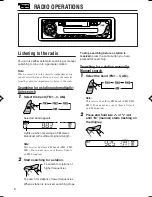
Page 6: ...g to tune in to a particular station Note When a cassette is in the cassette compartment you cannot select the tuner Be sure to eject the cassette from the cassette compartment to listen to the radio Searching for a station automatically Auto search 1 Select the band FM1 3 AM Note This receiver has three FM bands FM1 FM2 FM3 You can use any one of them to listen to an FM broadcast 2 Start searchin...

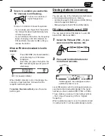
Page 7: ...e reception will be improved To restore the stereo effect press the same button again Storing stations in memory You can use one of the following two methods to store broadcasting stations in memory Automatic preset of FM stations SSM Strong station Sequential Memory Manual preset of both FM and AM stations FM station automatic preset SSM You can preset 6 local FM stations in each FM band FM1 FM2 ...

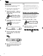
Page 8: ...and 8 1 Select the band FM1 3 AM 2 Select the number 1 6 for the preset station you want Manual preset You can preset up to 6 stations in each band FM1 FM2 FM3 and AM manually Ex Storing FM station of 92 5 MHz into the preset number 1 of the FM1 band 1 Select the band FM1 3 AM you want to store stations into in this example FM1 2 Tune in to a station in this example of 92 5 MHz 3 Press and hold th...

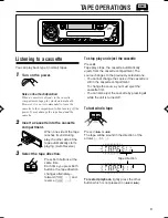
Page 9: ...n which is not pressed in 1 or TAPE OPERATIONS Listening to a cassette You can play back type I normal tapes 1 Turn on the power Note on One Touch Operation When a cassette is already in the cassette compartment tape play starts automatically However it is not recommended to leave the cassette in the compartment when turning off the power It may damage the tape head and the cassette 2 Insert a cas...

Page 10: ...ance R6 Right only VOL 2 Adjust the volume 00 min Volume 50 max 1 If you are using a two speaker system set the fader level to 00 2 Normally the and buttons work as the volume control buttons So you do not have to select VOL to adjust the volume level 2 Adjust the level 3 Repeat steps 1 and 2 to adjust the other items Turning on off the super bass function The super bass function allows you to mai...

Page 11: ...ments You can adjust the sound modes BEAT SOFT POP to your preference and store your own adjustments in memory There is a time limit in doing the following procedure If the setting is canceled before you finish start from step 1 again Ex When you select BEAT 1 Call up the sound mode you want to adjust See on the left column for details 2 To adjust the bass or treble level 1 Select BAS bass or TRE ...

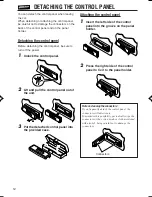
Page 12: ... and pull the control panel out of the unit 3 Put the detached control panel into the provided case Attaching the control panel 1 Insert the left side of the control panel into the groove on the panel holder 2 Press the right side of the control panel to fix it to the panel holder Note on cleaning the connectors If you frequently detach the control panel the connectors will deteriorate To minimize...

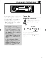
Page 13: ... display If this happens remove the magazine and set the discs correctly If no magazine is loaded in the CD changer NO MAG appears on the display If this happens insert the magazine in the CD changer If RESET 1 RESET 8 appears on the display something is wrong with the connection between this unit and the CD changer If this happens check the connection and make sure the cords are connected firmly ...

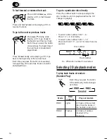
Page 14: ...acks of the next disc and so on RND2 Flashes All tracks of all discs inserted in the magazine To fast forward or reverse the track To go to the next or previous tracks Press and hold while playing a CD to fast forward the track Press and hold 4 while playing a CD to reverse the track Press briefly while playing a CD to go ahead to the beginning of the next track Each time you press the button cons...

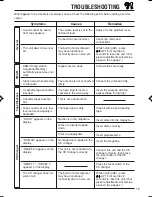
Page 15: ... the minimum level Connections are incorrect The built in microcomputer may have functioned incorrectly due to noise etc Signals are too weak The antenna is not connected firmly You have tried to insert a cassette in the wrong way This is not a malfunction The tape head is dirty No disc is in the magazine Discs are inserted upside down Discs are unplayable No magazine is loaded in the CD changer T...

Page 16: ...d drops out Do not play dirty or dusty tapes Do not touch the highly polished head with any metallic or magnetic tools To keep the tape clean Always store the cassettes in their storage cases after use Do not store cassettes in the following places Subject to direct sunlight With high humidity At extremely hot temperatures CAUTION Do not play the cassettes with peeling labels otherwise they can da...

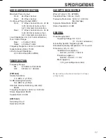
Page 17: ...Hz to 1 602 kHz FM Tuner Usable Sensitivity 11 3 dBf 1 0 µV 75 Ω 50 dB Quieting Sensitivity 16 3 dBf 1 8 µV 75 Ω Alternate Channel Selectivity 400 kHz 65 dB Frequency Response 40 Hz to 15 000 Hz Stereo Separation 35 dB Capture Ratio 2 0 dB AM Tuner Sensitivity 20 µV Selectivity 35 dB CASSETTE DECK SECTION Wow Flutter 0 15 WRMS Fast Wind Time 190 sec C 60 Frequency Response 50 Hz to 14 000 Hz Norma...

Page 18: ...EN 0105DTSMDTJEIN 2005 Victor Company of Japan Limited Having TROUBLE with operation Please reset your unit Refer to page of How to reset your unit ...

Page 19: ...e the red and black leads connected correctly Power cannot be turned on Is the yellow lead connected No sound from the speakers Is the speaker output lead short circuited Sound is distorted Is the speaker output lead grounded Are the terminals of L and R speakers grounded in common Noise interfere with sounds Is the rear ground terminal connected to the car s chassis using shorter and thicker cord...

Page 20: ...k Gray with black stripe White White with black stripe Green with black stripe Gray Green Purple with black stripe Purple Rear ground terminal To the remote lead of other equipment or automatic antenna if any 200 mA max Line out see diagram Left speaker rear Right speaker front Left speaker front Right speaker rear Ignition switch Antenna terminal To CD Changer only for KS FX384 see diagram You ca...

Reviews: