background image

EN 

3

Basic

Connections

CHECK CONTENTS

1

Make sure the package contains all of the accessories
listed in “Specifications” (

Z

 pg. 31).

SITUATE RECORDER

2

Place the recorder on a stable, horizontal surface.

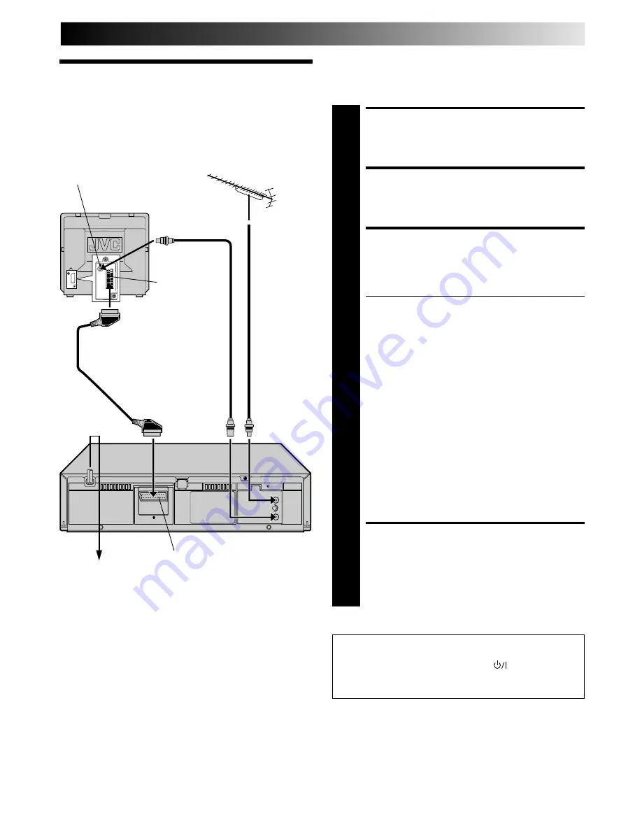
CONNECT RECORDER TO

TV

3

The connection method you use depends on the type
of TV you have.

RF CONNECTION

To Connect To A TV With NO AV Input Terminals . . .
a– Disconnect the TV aerial cable from the TV.
b– Connect the TV aerial cable to the ANT. IN jack

on the rear panel of the recorder.

c– Connect the provided RF cable between the RF

OUT jack on the rear panel of the recorder and
the TV’s aerial terminal.

Before operating the recorder, make sure the
TV’s channel is set to the VIDEO channel
(

Z

 pg. 5).

AV CONNECTION

To Connect To A TV With AV Input Terminals . . .
a– Connect the aerial, recorder and TV as per “RF

CONNECTION”.

b– Connect an optional SCART cable between the

AV1 IN/OUT socket on the rear panel of the
recorder and the TV’s 21-pin SCART connector.

Before operating the recorder, make sure the TV
is set to the VIDEO (or AV) mode.

CONNECT RECORDER TO

MAINS

4

Plug the end of the mains power cord into a mains
outlet.

It's essential that your video recorder be properly connected.
Follow these steps carefully. THESE STEPS MUST BE COM-
PLETED BEFORE ANY VIDEO OPERATION CAN BE PER-
FORMED.

INSTALLING YOUR NEW RECORDER

21-pin SCART
connector

Back of TV

Mains Power
Cord

Aerial terminal

After you plug the mains power cord into a mains outlet, the
Auto Set Up display appears on the TV screen and/or on the
recorder's front display panel when the 

 button on the

recorder/remote control is pressed for the first time to power
on the recorder 

Z

 pg. 4.

RF Cable
(provided)

TV Aerial
Cable

Mains outlet

Rear View

AV1 IN/OUT

21-pin SCART Cable

Summary of Contents for FST-GTK2I HR-J240E

Page 1: ... 5 8 COUNTER RESET COUNTER MEMORY STANDBY ON REVIEW M EN CONTENTS ENGLISH SAFETY FIRST 2 Safety Precautions 2 INSTALLING YOUR NEW RECORDER 3 Basic Connections 3 INITIAL SETTINGS 4 Auto Set Up 4 Video Channel Set 5 Clock Set 6 PLAYBACK 7 Basic Playback 7 Playback Features 8 RECORDING 11 Basic Recording 11 B E S T Picture System 12 On Screen Displays 14 Recording Features 15 TIMER RECORDING 16 Timer...

Page 2: ... when played back with this recorder 4 This recorder cannot be used for the SECAM L standard Use a SECAM L recorder to record SECAM L signals The STANDBY ON button does not completely shut off mains power from the unit but switches operating current on and off shows electrical power standby and shows ON For Italy It is declared that this product brand JVC conforms to the Ministry Decree n 548 of 2...

Page 3: ...the aerial recorder and TV as per RF CONNECTION b Connect an optional SCART cable between the AV1 IN OUT socket on the rear panel of the recorder and the TV s 21 pin SCART connector Before operating the recorder make sure the TV is set to the VIDEO or AV mode CONNECT RECORDER TO MAINS 4 Plug the end of the mains power cord into a mains outlet It s essential that your video recorder be properly con...

Page 4: ... that the aerial cable is connected to the recorder properly and turn off the recorder power once and turn the power back on to try Auto Set Up again If there is a power cut or if you press or MENU while Auto Set Up is in progress Auto Set Up will be interrupted be sure to turn off the recorder power once and try again 4 1 2 3 4 5 6 7 8 0 9 ATTENTION Once you have performed Auto Set Up even if the...

Page 5: ...nother channel between 32 40 TEST SIGNAL The channel on which the screen to the left appear clearly in step 3 is your Video Channel To view picture signals from the video recorder set your TV to the Video Channel Before starting make sure of the following The recorder s power should be off No cassette should be inserted in the recorder The connected TV s power should be on SET TV CHANNEL 1 Set you...

Page 6: ...ATE 5 Press STOP to set the date Press and hold either button to change the date by 15 days SET YEAR 6 Press DATE to set the year START CLOCK OPERATION 7 Press MENU Clock Set Turn on the TV and select the VIDEO channel or AV mode 4 1 4 7 3 8 1 2 3 4 5 6 7 8 0 9 2 1 3 MENU OK PUSH JOG CLOCK SET TIME DATE YEAR 00 00 01 01 00 MENU EXIT MAIN MENU FUNCTION SET TUNER SET CLOCK SET 5 MENU EXIT NOTE If th...

Page 7: ...is advanced past the start point press REW To go forward press FF START PLAYBACK 3 Press PLAY BEST appears blinking in the recorder s display panel during automatic tracking Z pg 12 STOP PLAYBACK 4 Press STOP on the remote or STOP EJECT on the recorder s front panel Then press STOP EJECT to remove the cassette Compact VHS camcorder recordings can be played on this video recorder Simply place the r...

Page 8: ...F P L A Y PAUSE REW T V P R O G TV PROG Slow Motion ACTIVATE SLOW MOTION PLAYBACK 1 During still picture press and hold PAUSE for 2 seconds then release Press and release again to return to still picture OR During still picture press and hold PUSH JOG or Release to return to still picture To resume normal playback press PLAY Still Picture Frame By Frame Playback PAUSE DURING PLAYBACK 1 Press PAUSE...

Page 9: ...eat Playback Information On Colour System You can also record SECAM signals or play back a MESECAM tape on this recorder When a MESECAM tape is played back MESECAM appears on the screen for about 5 seconds MESECAM is the designation for tapes with SECAM signals that have been recorded on a MESECAM compatible PAL video recorder NTSC Playback Your video recorder is equipped with NTSC circuitry that ...

Page 10: ...press C COUNTER MEMORY and M appears in front of the counter digits ACTIVATE COUNTER MEMORY 2 When you wish to return to the designated point press STOP and then REW or FF The tape rewinds or fast forwards and stops at about 0 00 00 automatically To cancel Counter Memory press C COUNTER MEMORY again Instant ReView Simply by pressing a single button the recorder power comes on rewinds and begins pl...

Page 11: ... on the recorder PAUSE RESUME RECORDING 4 Press PAUSE Press PLAY to resume recording STOP RECORDING 5 Press STOP on the remote control or STOP EJECT on the recorder Then press STOP EJECT to remove the cassette NUMBER PLAY PAUSE STOP RECORD B E S T takes place at the beginning of the first recording after inserting the cassette Z pg 12 Recording Resume Function If there is a power outage during rec...

Page 12: ...T by pressing PUSH JOG fi then press OK SELECT MODE 5 Place the pointer next to ON by pressing PUSH JOG fi then press OK RETURN TO NORMAL SCREEN 6 Press MENU START RECORDING 7 Press and hold RECORD and PLAY on the remote or press RECORD on the recorder The recorder spends approximately 7 seconds assessing the condition of the tape then begins recording When the BEST indicator begins blinking that ...

Page 13: ...2 through 6 on page 12 BEST only appears at the beginning of automatic tracking Even though it doesn t appear after that the B E S T function is operative Playback The recorder assesses the quality of the tape once you initiate playback When watching a tape recorded with B E S T set to ON it is recommended that you leave B E S T on during playback as well ATTENTION Since the B E S T system works b...

Page 14: ...t is and go to step 6 If you don t want the displays to appear press PUSH JOG fi to place the pointer next to OFF then press OK RETURN TO NORMAL 6 Press MENU NOTES When you use this recorder as the player for editing be sure to set O S D to OFF before starting During playback the operation mode indicators may be disturbed depending on the type of tape being used FUNCTION SET AUTO TIMER O S D B E S...

Page 15: ...ed START RECORDING 1 Press RECORD on the recorder ENGAGE ITR MODE 2 Press RECORD again blinks and 0 30 appears on the front display panel SET RECORDING DURATION 3 If you want to record for more than 30 minutes press RECORD to extend the time Each press extends recording time by 30 minutes NOTE You can only perform ITR using the RECORD button on the recorder s front panel Elapsed Recording Time Ind...

Page 16: ...1 appears ENTER PROGRAMME START TIME 3 Press START to enter the time you want recording to start Press and hold START to move in 30 minute increments or press and release repeatedly to move 1 minute at a time ENTER PROGRAMME STOP TIME 4 Press STOP to enter the time you want recording to stop ENTER PROGRAMME DATE 5 Press DATE The current date appears on screen The date you enter appears in its plac...

Page 17: ...ation disappear 4 1 4 7 3 8 1 2 3 4 5 6 7 8 0 9 2 1 3 TIMER WEEKLY D A I L Y NOTES To timer record a satellite broadcast through a satellite tuner connected to the AV1 IN OUT connector on the back of the recorder in step 6 set TV PROG to AUX by pressing TV PROG Before the selected programme begins select the appropriate channel on the satellite tuner then set the tuner s timer If your satellite tu...

Page 18: ...CORDING cont MAIN MENU FUNCTION SET TUNER SET CLOCK SET 5 MENU EXIT FUNCTION SET AUTO TIMER O S D B E S T 5 MENU EXIT AUTO TIMER ON OFF 5 MENU EXIT Check And Cancel Programmes ACCESS PROGRAMME SCREEN 1 Press PROG CHECK If the recorder is turned on and the TV is set to its VIDEO channel or AV mode you can check program information on screen Each time you press PROG CHECK the next programme s inform...

Page 19: ... NUMBER key 0 and or TV PROG so that AU appears on the display panel START SOURCE PLAYER 3 Engage its Play mode START RECORDING DECK 4 Engage its Record mode NOTE All necessary cables can be obtained from your dealer RF Cable provided VIDEO CHAN NEL or AV mode Another recorder Another recorder Player Your recorder Your recorder TV Receiver TV Receiver Recorder Recorder Player 4 1 4 7 3 8 1 2 3 4 5...

Page 20: ...s to the recorder s AUDIO VIDEO input connectors SET RECORDER S INPUT MODE 2 Press NUMBER key 0 and or TV PROG so that AU appears on the display panel START CAMCORDER 3 Engage its Play mode START RECORDER 4 Engage its Record mode EDITING cont 4 1 4 7 3 8 1 2 3 4 5 6 7 8 0 9 2 1 3 Player AUDIO OUT VIDEO OUT Audio Video signals Cable adapter Camcorder Your recorder NUMBER 0 TV PROG ...

Page 21: ... 2 Press MENU twice ACCESS TUNER SET SCREEN 3 Press PUSH JOG fi to place the pointer next to TUNER SET then press OK SELECT AUTO CH SET MODE 4 Press PUSH JOG fi to place the pointer next to AUTO CH SET then press OK Auto Channel Set will start RETURN TO NORMAL SCREEN 5 Press MENU 4 1 4 7 3 8 1 2 3 4 5 6 7 8 0 9 2 1 3 MENU OK PUSH JOG IMPORTANT Since your video recorder memorizes all detected stati...

Page 22: ...CT BAND 3 Press PUSH JOG fi to place the pointer next to the band of your choice then press OK to initiate Manual Channel Set SET DESIRED STATION 4 The screen to the right appears when a station is detected To store the detected station place the pointer next to STORE by pressing PUSH JOG fi then press OK If you do not want to store the station press PUSH JOG fi to place the pointer next to CONTIN...

Page 23: ... Swap Channel Positions Example To swap CH03 and CH09 5 ACCESS TUNER SET SCREEN 1 Perform steps 1 3 of Auto Channel Set on page 21 ACCESS CHANNEL LIST 2 Press PUSH JOG fi to place the pointer next to CH EDIT then press OK SELECT POSITION e g 03 3 Press PUSH JOG fi until the section of CH 03 begins blinking then press OK Only 03 will blink SELECT POSITION e g 09 4 Press NUMBER keys to input 0 and 9...

Page 24: ... 3 Press PUSH JOG fi until the channel you want to tune begins blinking then press OK twice The FRQ number for that channel starts blinking PERFORM TUNING 4 Press PUSH JOG fi until the picture becomes clearer then press OK Repeat steps 3 and 4 RETURN TO NORMAL SCREEN 5 Press MENU TUNER SET cont CH FRQ CH FRQ 01 150 07 229 02 165 08 237 03 195 09 355 04 205 10 365 05 213 11 374 06 221 12 384 5 FINE...

Page 25: ... recording the end of the recording before the pause is overlapped by the beginning of the continuation of recording Why does this happen A This is normal It reduces distortion at the pause and resume points Q Can the video recorder indefinitely remain in the Record Pause mode A No The video recorder goes to its Stop mode auto matically after 5 minutes to protect the heads Q What happens if the ta...

Page 26: ...s not set to the VIDEO channel the recorder s VIDEO channel has not been correctly set If you re using the AV connection the TV receiver is not set to the AV mode This is normal The automatic tracking mode is engaged The automatic tracking mode is engaged The video heads may be dirty CORRECTIVE ACTION If you are using the RF OUT connec tion set the TV receiver to the VIDEO channel Z pg 5 Perform V...

Page 27: ...ncorrectly The timer is not engaged Timer recording is in progress The timer is engaged but there s no cassette loaded The loaded cassette has had its Record Safety tab removed TIMER has been pressed when there are no programs in memory or the timer record information has been programmed incorrectly The end of the tape was reached during timer recording CORRECTIVE ACTION Position the camcorder so ...

Page 28: ...pg 7 6 COUNTER MEMORY Button Z pg 10 7 COUNTER RESET Button Z pg 15 8 Display Panel Z pg 29 9 Infrared Beam Receiving Window 0 TV PROG Buttons Z pg 11 DISPLAY Button Z pg 15 RECORD Button Z pg 11 STOP EJECT Button Z pg 7 PAUSE Button Z pg 8 REAR VIEW ANT IN RF OUT 40 32 AV1 IN OUT 3 2 4 5 1 4 RF Output Channel Adjustment Screw Z pg 5 5 RF OUT Connector Z pg 3 1 Mains Power Cord Z pg 3 2 AV1 IN OUT...

Page 29: ...m Display Z pg 12 2 Symbolic Mode Indicators 3 Timer Indicator Z pg 17 4 Counter Memory Indicator Z pg 10 5 Channel Mode Display Z pg 11 Channel position 1 will be displayed as CH 1 Clock Display Z pg 6 6 Instant REVIEW Indicator Z pg 10 7 Cassette Loaded Mark 8 Counter Display Z pg 15 REVIEW M 1 3 4 2 8 7 5 6 ...

Page 30: ...ME 6 7 8 DAILY 0 AUX 9 WEEKLY TV VCR MONITOR CANCEL C RESET PROG CHECK 4 TIMER TV PROG DATE STOP START PROG MENU OK C MEMORY TV VOL TV VOL DISPLAY 2 1 3 EXPRESS PROGRAMMING PUSH JOG Press and hold TV button while pressing TV PROG TV VCR REW 9 u y 3 5 4 1 6 2 o i e r t 7 8 p q w 0 Installing Batteries 1 Open the battery compartment cover 2 Insert 2 R6 size batteries provided in the correct directio...

Page 31: ...elds Recording system Rotary two head helical scan system Signal to noise ratio 45 dB Horizontal resolution 250 lines Frequency range 70 Hz to 10 000 Hz Input Output 21 pin scart connectors x 1 IN OUT x 1 TUNER TIMER TV channel storage capacity 99 positions AUX position AU Tuning system Frequency synthesized tuner Channel coverage VHF 47 89 104 300 302 470MHz UHF 470 862MHz Aerial output UHF chann...

Page 32: ...COPYRIGHT 1997 VICTOR COMPANY OF JAPAN LTD E Printed in Japan 0697YOV UN VP VICTOR COMPANY OF JAPAN LIMITED HR J240E EN ...

Reviews: