


1-14 (No.MB353)
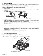
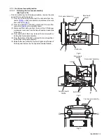
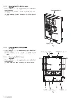
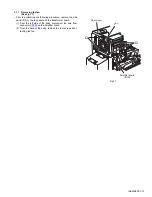
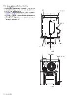
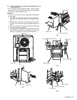
3.1.8 Removing the amplifier board/ heat sink
(See Fig.18, 19)
• Prior to performing the following procedure, remove the side
panel (R)/(L), the top panel, the main board, the transformer
board, the tuner pack and the fan.
(1) From top of the body, disconnect the wire from connector
CN101
and
CN204
on the amplifier board.
(2) From top of the body, remove the five screws
R
attaching
the amplifier board.
(3) From the back of the body, remove the two screws
T
at-
taching the amplifier board.
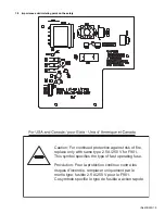
Fig.18
Fig.19
CN101
CN204
Amplifier board
R
R
Rear panel
Rear panel
Amplifier board
T
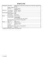
Summary of Contents for FS-G5
Page 20: ...1 20 No MB353 SECTION 4 ADJUSTMENT This service manual does not describe ADJUSTMENT ...
Page 25: ... M E M O ...
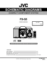
Page 30: ...Standard schematic diagrams Front Power supply section 2 5 ...
Page 32: ...Main section 2 7 ...
Page 33: ...2 8 ...
Page 34: ...Amp section 2 9 ...
Page 35: ...2 10 ...
Page 36: ...CD section 2 11 ...
Page 37: ...2 12 ...
Page 39: ... Cu melting point 219 Centigrade 2 14 ...
Page 41: ...ng point 219 Centigrade 2 16 ...
Page 43: ...solder used in the board material Sn Ag Cu melting point 219 Centigrade 2 18 ...
Page 45: ...in the board material Sn Ag Cu melting point 219 Centigrade 2 20 ...
Page 49: ... M E M O ...


