

1-18 (No.YF414<Rev.002>)
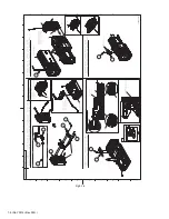
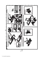
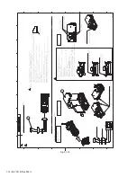
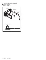
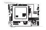
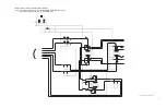
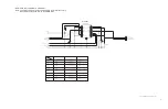
Fig.3-2-2
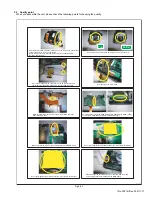
Make sure that the CMOS FPC is not caught between the boards.
Pay attention to use the correct fastening screw for the junction board.
(The shortest screw. Using a wrong screw will damage the OP.)
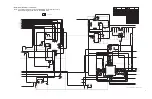
Make sure that the FFC between TRIG PWB and MAIN PWB is on top of
the TRIG PWB connector.
(Pay attention to prevent it from interfering with the HDMI terminal.)
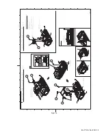
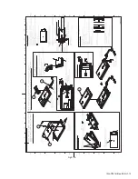
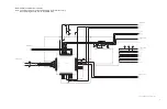
Take note that the monitor FPC has been changed from the
conventional 2.5 diameter to 1.5.
As the tabs are located more inwards than past models, remove the
M.PLATE ASSY from the hinge's side such as by using a guitar pick.
(Unable to remove with your finger nails)
Attach the monitor FPC to the spacer on the monitor board. Pay
Vattention to the position to attach.
(Adhered with transparent double-sided tape)
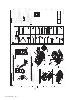
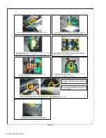
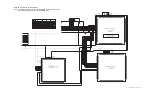
Before removing the TOP cover, remove the jig cover.
(Otherwise, the rib illustrated in the photo will break.)
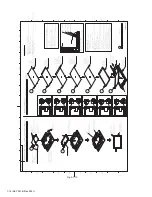
When removing the M.PLATE ASSY, dismantle the HINGE COVER. Dismantle from one of the sides,
followed by the other, paying attention not to damage the FPC, as illustrated in the photo.
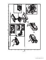
As the opening of the M.PLATE ASSY is smaller than
that of the FPC, opening it in this way will break the
FPC wires.
Make sure to check for any damage immediately after
opening, and replace the FPC with a new one if
scratches are found.
< 2/2 >
Summary of Contents for Everio GZ-V500BUA
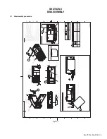
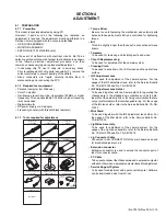
Page 5: ... No YF414 Rev 002 1 5 SECTION 3 DISASSEMBLY 3 1 Disassembly procedure Fig 3 1 1 CLEANER ...
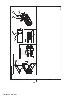
Page 6: ...1 6 No YF414 Rev 002 Fig 3 1 2 FINAL 5 5 ...
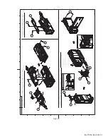
Page 7: ... No YF414 Rev 002 1 7 Fig 3 1 3 FINAL 4 5 ...
Page 8: ...1 8 No YF414 Rev 002 Fig 3 1 4 FINAL 3 5 ...
Page 9: ... No YF414 Rev 002 1 9 Fig 3 1 5 FINAL 2 5 ...
Page 11: ... No YF414 Rev 002 1 11 Fig 3 1 7 UPPER 4 4 ...
Page 12: ...1 12 No YF414 Rev 002 Fig 3 1 8 UPPER 3 4 ...
Page 13: ... No YF414 Rev 002 1 13 Fig 3 1 9 UPPER 2 4 ...
Page 14: ...1 14 No YF414 Rev 002 Fig 3 1 10 UPPER 1 4 ...
Page 15: ... No YF414 Rev 002 1 15 Fig 3 1 11 CIS 5 5 ...
Page 16: ...1 16 No YF414 Rev 002 Fig 3 1 12 CIS 4 5 ...
Page 49: ...PARTS LIST CAMCORDER GZ V505BTW No YF414 Rev 001 1 15 ...


