background image

1-56 (No.MB531)

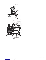
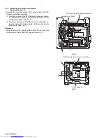
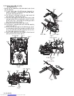
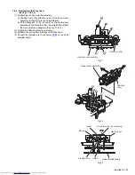
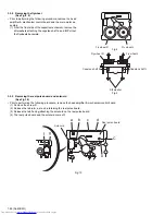
3.4.4 Removing the flywheel 

(See Fig.8, 9)

• Prior to performing the following procedure, remove the head

amplifier board and the main motor assembly.

(1) From the front side of the cassette mechanism, remove the

slit washers attaching the capstan shaft L and R.

(2) Pull out the flywheels backward.

Fig.8

Fig.9

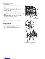
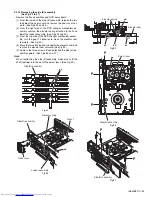
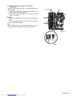
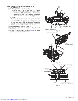
3.4.5 Removing the cassette switch board and solenoid 

(See Fig.10)

• Prior to performing the following procedure, remove the head

amplifier board.

(1) Remove the screw 

C

.

(2) Release the tab a, b, c, d and e retaining the cassette

switch board.

(3) Release the tab f and g attaching the solenoid on the cas-

sette switch board.

(4) The cassette switch board and solenoid come off.

Fig.10

Fly wheel R

Fly wheel L

Capstan shaft R

Capstan shaft L

Fly wheel R

Slit washer

Fly wheel L

a

f

g

b

d

e

C

Cassette switch board

Solenoid

c

Summary of Contents for DX-T66EE

Page 1: ...X T66UX DX T66UY DX T66UG DX T66UN Lead free solder used in the board material Sn Ag Cu melting point 219 Centigrade TABLE OF CONTENTS 1 PRECAUTION 1 6 2 SPECIFIC SERVICE INSTRUCTIONS 1 9 3 DISASSEMBLY 1 10 4 ADJUSTMENT 1 62 5 TROUBLESHOOTING 1 65 SUPER VIDEO CA DXT66 SP DXT99W SP DXT66F SP DXT66F CA DXT77 SP DXT77S SP DXT77S SP DXT99W SP DXT99F SP DXT99F SP DXT77C SUPER VIDEO CA DXT99 SP DXT99S S...

Page 2: ... VIDEO composite 1 V p p 75 Ω S VIDEO Y luminance 1 V p p 75 Ω C chrominance burst NTSC 0 286 V p p 75 Ω PAL 0 3 V p p 75 Ω COMPONENT Interlace Progressive Y 1 V p p 75 Ω PB PR 0 7 V p p 75 Ω Speaker Terminals 4 Ω 16 Ω front speakers subwoofers 6 Ω 16 Ω surround center speakers Tuner section FM tuning range 87 50 MHz 108 00 MHz AM MW tuning range 531 kHz 1 710 kHz for austraria 531 kHz 1 710 kHz a...

Page 3: ...chrominance burst NTSC 0 286 V p p 75 Ω PAL 0 3 V p p 75 Ω COMPONENT Interlace Progressive Y 1 V p p 75 Ω PB PR 0 7 V p p 75 Ω Speaker Terminals 4 Ω 16 Ω front speakers subwoofers 6 Ω 16 Ω surround center speakers Tuner section FM tuning range 87 50 MHz 108 00 MHz AM MW tuning range 531 kHz 1 710 kHz at 9 kHz for asia 530 kHz 1 710 kHz at 10 kHz for asia 522 kHz 1 629 kHz for russia Disc player se...

Page 4: ...7 V p p 75 Ω Speaker Terminals 4 Ω 16 Ω front speakers subwoofers 6 Ω 16 Ω surround center speakers Tuner section FM tuning range 87 50 MHz 108 00 MHz AM MW tuning range 531 kHz 1 710 kHz at 9 kHz for asia 530 kHz 1 710 kHz at 10 kHz for asia 522 kHz 1 629 kHz for russia Disc player section Playable disc DVD Video DVD Audio CD VCD SVCD CD R CD RW recorded in Audio CD Video CD Super Video CD for ma...

Page 5: ...cm cone 1 Tweeter 2 cm dome 1 Power handling capacity 150 W Impedance 4 Ω Frequency range 35 Hz 25 000 Hz Sound pressure level 85 dB W m Dimensions W H D approx 204 mm 460 mm 273 mm Mass approx 5 2 kg each Subwoofer Type 1 Way Bass Reflex Magnetically Shielded Type Speaker systems 20 cm cone 1 Power handling capacity 150 W Impedance 4 Ω Frequency range 35 Hz 5 000 Hz Sound pressure level 88 dB W m...

Page 6: ...ack control shafts etc to be sure the product is safe to operate without danger of electrical shock Do not use a line isolation transformer during this check Plug the AC line cord directly into the AC outlet Using a Leakage Current Tester measure the leakage current from each exposed metal parts of the cabinet particular ly any exposed metal part having a return path to the chassis to a known good...

Page 7: ...he optical pickup The tester s internal power source can easily destroy the laser diode 1 6 Handling the traverse unit optical pickup 1 Do not subject the traverse unit optical pickup to strong shocks as it is a sensitive complex unit 2 Cut off the shorted part of the flexible cable using nippers etc after replacing the optical pickup For specific details refer to the replacement procedure in the ...

Page 8: ... uses visible and or invisible laser radiation and is equipped with safety switches which prevent emission of radiation when the drawer is open and the safety interlocks have failed or are defeated It is dangerous to defeat the safety switches 5 CAUTION If safety switches malfunction the laser is able to function 6 CAUTION Use of controls adjustments or performance of procedures other than those s...

Page 9: ... No MB531 1 9 SECTION 2 SPECIFIC SERVICE INSTRUCTIONS This service manual does not describe SPECIFIC SERVICE INSTRUCTIONS ...

Page 10: ... remove the six screws A attaching the metal cover See Fig 1 2 From the back side of the main body remove the eight screws B attaching the metal cover See Fig 2 3 Remove the metal cover from the main body while lifting the rear section of the metal cover in the direction of the ar row See Fig 1 Fig 1 Fig 2 Metal cover A A Metal cover B B B ...

Page 11: ...k of the connector CN105 on the primary board in the direction of the arrow See Fig 4 4 From the both side of the main body remove the two screws C attaching the front panel assembly to the main body See Fig 3 4 5 From the bottom side of the main body remove the two screws D attaching the front panel assembly See Fig 5 6 From the both side of main body release the claws a and remove the front pane...

Page 12: ... the metal cover 1 From the back side of the main body remove the two screws E attaching the tuner to the rear panel 2 Take out the tuner from the main body and disconnect the card wire from the connector CN1 on the tuner Fig 6 E Tuner CN1 Tuner Rear panel ...

Page 13: ...he two screws F attaching the DVD changer mechanism assembly on the mecha chassis See Fig 8 4 Take out the DVD changer mechanism assembly from the main body and disconnect the card wire from the connector CN930 on the video board See Fig 8 Reference When the resolution of the DVD changer mechanism assem bly is done sequentially release the claws b of the tray fitting and remove the five tray fitti...

Page 14: ...crews G attaching the video board to the rear panel See Fig 10 2 From the top side of the main body disconnect the card wires from the connectors CN920 CN931 on the video board See Fig 11 3 Take out the video board in the direction of the arrow while removing it from the sections c of the mecha chassis See Fig 11 Fig 10 Fig 11 Video board Rear panel G Mecha chassis CN920 CN931 c c Video board ...

Page 15: ...4 on the amplifier 2 board See Fig 13 DX T99 3 Remove the joints d and remove the rear cover See Fig 12 From the left side of the main body disconnect the wire from the connector CN604 on the amplifier 2 board See Fig 13 For DX T66 DX T77 4 Release the two joints e of the fan bracket in the direction of the arrow and take out the fan with the fan bracket See Fig 13 Reference Remove the fan from th...

Page 16: ...99 DX T77 2 Remove the two screws J and ten screws K attaching the rear panel For DX T66 3 Release the section f of the rear panel and remove the joints g of the mecha chassis in the direction of the arrow 4 Remove the rear panel from the main body Fig 14 Mecha chassis Rear panel g f f g K K K K J DX T99 DX T77 DX T66 Mecha chassis Rear panel g f f g K K K K J K K ...

Page 17: ...of the main board 3 Disconnect the main board from the bridge board toward this side while releasing the claw h of the connector CN850 on the main board 4 Disconnect the main board from the surround terminal board in the direction of the arrow while releasing the claw I of the connector CN860 on the surround terminal board For DX T99 DX T77 Note When releasing the claws h j take care not to break ...

Page 18: ...heat sink See Fig 18 3 1 10 Removing the amplifier 1 and amplifier 2 boards See Fig 16 to 18 For DX T77 DX T66 Remove the metal cover tuner fan rear panel and main board 1 From the right side of the main body remove the crew N attaching the earth wires to the bottom chassis See Fig 16 Reference After reassembling fix the earth wires with the spacer as before See Fig 16 2 Disconnect the amplifier 2...

Page 19: ... 18 P P P P P P Amplifier 1 board Amplifier 2 board Leaf spring Heat sink P P DX T77 Amplifier 1 board Amplifier 2 board Leaf spring Heat sink P P DX T99 Amplifier 1 board Amplifier 2 board Leaf spring Heat sink P DX T66 ...

Page 20: ...101 CN102 on the forward side of the primary board 5 Disconnect the power cord from the connector CN100 on the primary board 6 Take out the primary board from the main body Fig 19 3 1 12 Removing the primary board See Fig 20 Remove the metal cover tuner fan rear panel main board amplifier 1 board amplifier 2 board and primary board 1 Remove the wire holders bundling the wires References After reas...

Page 21: ...ing the power transformer See Fig 21 Remove the metal cover tuner fan rear panel main board amplifier 1 board amplifier 2 board primary board and bridge board 1 Remove the four screws T attaching the power transform er 2 Take out the power transformer from the main body Fig 21 3 1 15 Removing the FL board See Fig 22 Remove the metal cover and front panel assembly 1 From the inside of the front pan...

Page 22: ...ront panel assembly Reference Remove the trans shield as required Fig 23 3 1 17 Removing the cassette B mechanism assembly See Fig 24 Remove the metal cover and front panel assembly 1 From the inside of the front panel assembly remove the four screws V and screw W attaching the cassette B mech anism assembly 2 Take out the cassette B mechanism assembly from the front panel assembly Reference Remov...

Page 23: ... the front panel assembly remove the two screws X and remove the support 1 board See Fig 26 3 Remove the screw Y and remove the support 2 board See Fig 26 4 Take out the microphone amplifier board from the front panel assembly References After attaching the microphone amplifier board fix the card wire the spacer as before Fig 25 Fig 26 Front panel assembly Microphone volume knob Support 2 board Sp...

Page 24: ...D changer mechanism assembly See Fig 3 4 From the right side of the DVD changer mechanism as sembly draw out the tray assemblies toward the front while pushing the part b of the side R assembly See Figs 4 and 5 Note The tray can be locked if all tray assemblies are at tached 5 From the topside of the DVD changer mechanism assem bly move the stopper tabs c in the direction of the arrow and release ...

Page 25: ... No MB531 1 25 Fig 3 Fig 4 Fig 5 Open det lever b Tray assemblies Side R assembly c Tray assembly ...

Page 26: ...s B attaching the DVD servo board See Fig 7 5 From the reverse side of the DVD servo board release the lock of the connector CN101 in the direction of the arrow and disconnect the card wire See Fig 8 Caution Unsolder the solders from the short land sections d after reas sembling See Fig 6 3 2 3 Removing the switch board See Fig 7 1 From the bottom side of the DVD changer mechanism as sembly remove...

Page 27: ...motor board See Fig 10 5 Disconnect the card wire from the connector CN1 on the forward side of the motor board See Fig 10 Note When connecting the card wire let the card wire through the slots h of the motor board See Fig 10 Reference You need not to remove the tray assemblies and in such case move it 3 2 5 Removing the motor See Fig 10 Remove the motor board 1 From the reverse side of the motor ...

Page 28: ... the bottom side of the DVD changer mechanism as sembly remove the three screws F attaching the DVD traverse mechanism assembly 2 Remove the wires from the section j 3 Take out the DVD traverse mechanism assembly from the DVD changer mechanism assembly Fig 11 F F j F DVD changer mechanism assembly DVD traverse mechanism assembly ...

Page 29: ...move the two screws H attaching the rack arm spring and rack arm See Fig 14 8 Pull the guide shaft from the DVD pickup in the direction of the arrow See Fig 14 3 2 8 Attaching the DVD pickup See Figs 12 to 14 1 Attach the guide shaft to the DVD pickup and attach the rack arm spring and rack arm with the screws H See Fig 14 2 Attach the section q of the DVD pickup to the C TM chassis first and atta...

Page 30: ...1 30 No MB531 Fig 14 Fig 15 DVD pickup Rack arm Rack arm spring H Guide shaft 2 2 2 1 Screw shaft gear DVD pickup Connector ...

Page 31: ...om the soldered sections r on the spindle motor board See Fig 16 2 From the bottom side of the DVD traverse mechanism as sembly remove the three screws J attaching the spindle motor board See Fig 17 Reference When attaching the spindle motor board let the card wire through the hole s on the C TM chassis See Fig 17 Fig 16 Fig 17 r Spindle motor board DVD traverse mechanism assembly J C TM chassis D...

Page 32: ... Fig 18 3 Remove the screw shaft from the section v and remove it in the direction of the arrow See Fig 19 4 Remove the middle gear See Fig 19 5 Remove the screw L attaching the feed motor to the C TM chassis See Fig 19 6 Remove the wires from the soldered sections w on the spindle motor board See Fig 19 7 Take out the feed motor from the motor base Reference After attaching the feed motor pass th...

Page 33: ...r CN3 on the tray switch board from the motor board and detach the side L in an upward direction See Fig 21 3 Remove the screw N attaching the tray switch board to the side L See Fig 22 4 Release the joint tab y of the side L in the direction of the arrow 1 and release the joint tab z while removing the tray switch board in the direction of the arrow 2 See Fig 22 Fig 20 Fig 21 Fig 22 M SIde L M DV...

Page 34: ...D changer mechanism assem bly turn the gear 1 clockwise to move the elevator cam rearward See Fig 25 4 Move the two slots ac and joint ad of the elevator cam and remove the elevator cam outward See Fig 25 5 Remove the three screws P and detaches the side R as sembly upward See Figs 26 and 27 Note When reattaching the side R assembly make sure to fit the shaft part ae into the slot of the select le...

Page 35: ...nts ag to detach from the rack holder See Fig 30 4 Release the rod L from part ah See Fig 30 5 Turn the gear 1 clockwise again to move the lifter assembly upward See Fig 31 6 Remove the lifter assembly from the DVD changer mecha nism assembly upward at the positions ai where the four pins on the both sides of the lifter assembly fit to the notch es of the loader assembly See Fig 31 7 Move the lift...

Page 36: ...res 2 Remove the two screws Q and take out the sensor board with the SV resistor Reference Remove the soldered section ap on the sensor board as re quired When reassembling pass the wires through the slot ak of the sensor board as before Note When reattaching the SV resister fit the projection am on the bottom of the SV resister into slot an of the sensor slider Fig 33 Q Q ap Sensor board ak SV re...

Page 37: ...y upward See Fig 34 4 Turn the gear 2 clockwise to move the sub tray remaining inside the lifter assembly toward the front then pull out See Fig 34 5 Take out the disc on the sub tray See Fig 35 6 After clearing away the disc insert the sub tray into the main tray See Fig 36 Note When reattaching the sub tray move the tray stopper on the bottom of the main tray in the direction of the arrow to loc...

Page 38: ...1 38 No MB531 Fig 36 Fig 37 Main tray Sub tray Tray stopper Tray stopper ...

Page 39: ...hanger mechanism assembly See Fig 3 4 From the right side of the DVD changer mechanism as sembly draw out the tray assemblies toward the front while pushing the part b of the side R assembly See Figs 4 and 5 Note The tray can be locked if all tray assemblies are at tached 5 From the topside of the DVD changer mechanism assem bly move the stopper tabs c in the direction of the arrow and release the...

Page 40: ...1 40 No MB531 Fig 3 Fig 4 Fig 5 Open det lever b Tray assemblies Side R assembly c Tray assembly ...

Page 41: ...ws B attaching the DVD servo board See Fig 7 5 From the reverse side of the DVD servo board release the lock of the connector CN101 in the direction of the arrow and disconnect the card wire See Fig 8 Caution Unsolder the solders from the short land sections d after reas sembling See Fig 6 3 3 3 Removing the switch board See Fig 7 1 From the bottom side of the DVD changer mechanism as sembly remov...

Page 42: ...motor board See Fig 10 5 Disconnect the card wire from the connector CN1 on the forward side of the motor board See Fig 10 Note When connecting the card wire let the card wire through the slots h of the motor board See Fig 10 Reference You need not to remove the tray assemblies and in such case move it 3 3 5 Removing the motor See Fig 10 Remove the motor board 1 From the reverse side of the motor ...

Page 43: ...m the bottom side of the DVD changer mechanism as sembly remove the three screws F attaching the DVD traverse mechanism assembly 2 Remove the wires from the section j 3 Take out the DVD traverse mechanism assembly from the DVD changer mechanism assembly Fig 11 F F j F DVD changer mechanism assembly DVD traverse mechanism assembly ...

Page 44: ...move the two screws H attaching the rack arm spring and rack arm See Fig 14 8 Pull the guide shaft from the DVD pickup in the direction of the arrow See Fig 14 3 3 8 Attaching the DVD pickup See Figs 12 to 14 1 Attach the guide shaft to the DVD pickup and attach the rack arm spring and rack arm with the screws H See Fig 14 2 Attach the section q of the DVD pickup to the C TM chassis first and atta...

Page 45: ... No MB531 1 45 Fig 14 Fig 15 DVD pickup Rack arm Rack arm spring H Guide shaft 2 2 2 1 Screw shaft gear DVD pickup Connector ...

Page 46: ...om the soldered sections r on the spindle motor board See Fig 16 2 From the bottom side of the DVD traverse mechanism as sembly remove the three screws J attaching the spindle motor board See Fig 17 Reference When attaching the spindle motor board let the card wire through the hole s on the C TM chassis See Fig 17 Fig 16 Fig 17 r Spindle motor board DVD traverse mechanism assembly J C TM chassis D...

Page 47: ...e Fig 18 3 Remove the screw shaft from the section v and remove it in the direction of the arrow See Fig 19 4 Remove the middle gear See Fig 19 5 Remove the screw L attaching the feed motor to the C TM chassis See Fig 19 6 Remove the wires from the soldered sections w on the spindle motor board See Fig 19 7 Take out the feed motor from the motor base Reference After attaching the feed motor pass t...

Page 48: ... CN3 on the tray switch board from the motor board and detach the side L in an upward direction See Fig 21 3 Remove the screw N attaching the tray switch board to the side L See Fig 22 4 Release the joint tab y of the side L in the direction of the arrow 1 and release the joint tab z while removing the tray switch board in the direction of the arrow 2 See Fig 22 Fig 20 Fig 21 Fig 22 M SIde L M DVD...

Page 49: ...D changer mechanism assem bly turn the gear 1 clockwise to move the elevator cam rearward See Fig 25 4 Move the two slots ac and joint ad of the elevator cam and remove the elevator cam outward See Fig 25 5 Remove the three screws P and detaches the side R as sembly upward See Figs 26 and 27 Note When reattaching the side R assembly make sure to fit the shaft part ae into the slot of the select le...

Page 50: ...ints ag to detach from the rack holder See Fig 30 4 Release the rod L from part ah See Fig 30 5 Turn the gear 1 clockwise again to move the lifter assembly upward See Fig 31 6 Remove the lifter assembly from the DVD changer mecha nism assembly upward at the positions ai where the four pins on the both sides of the lifter assembly fit to the notch es of the loader assembly See Fig 31 7 Move the lif...

Page 51: ...res 2 Remove the two screws Q and take out the sensor board with the SV resistor Reference Remove the soldered section ap on the sensor board as re quired When reassembling pass the wires through the slot ak of the sensor board as before Note When reattaching the SV resister fit the projection am on the bottom of the SV resister into slot an of the sensor slider Fig 33 Q Q ap Sensor board ak SV re...

Page 52: ... upward See Fig 34 4 Turn the gear 2 clockwise to move the sub tray remaining inside the lifter assembly toward the front then pull out See Fig 34 5 Take out the disc on the sub tray See Fig 35 6 After clearing away the disc insert the sub tray into the main tray See Fig 36 Note When reattaching the sub tray move the tray stopper on the bottom of the main tray in the direction of the arrow to lock...

Page 53: ... No MB531 1 53 Fig 36 Fig 37 Main tray Sub tray Tray stopper Tray stopper ...

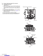
Page 54: ...The head turns counterclockwise as you turn the flywheel R counterclockwise See Fig 2 and 3 3 Disconnect the flexible wire from connector CN48 on the head amplifier board 4 Remove the spring from the back of the head 5 Loosen the azimuth screw for reversing attaching the head 6 Remove the head on the front side of the head mount Fig 1 Fig 2 Fig 3 Cassette mechanism assembly Fly wheel R Trigger arm...

Page 55: ...essary unsolder the 4 pin wire soldered to the main mo tor 3 4 3 Removing the main motor See Fig 4 to 7 1 Remove the two screws B 2 Half raise the motor and remove the capstan belt from the motor pulley Attention Be careful to keep the capstan belt from grease When reas sembling refer to Fig 6 and 7 for attaching the capstan belt Fig 4 Fig 5 Fig 6 Fig 7 Head amplifier board A A CN48 CN41 4pin wire...

Page 56: ...ig 9 3 4 5 Removing the cassette switch board and solenoid See Fig 10 Prior to performing the following procedure remove the head amplifier board 1 Remove the screw C 2 Release the tab a b c d and e retaining the cassette switch board 3 Release the tab f and g attaching the solenoid on the cas sette switch board 4 The cassette switch board and solenoid come off Fig 10 Fly wheel R Fly wheel L Capst...

Page 57: ... the holes P and V the slots O U and Q of the mechanism sub assembly See Fig 11 to 13 2 Tighten the azimuth screw for reversing 3 Reattach the spring from the back of the Play head 4 Connect the flexible wire to connector CN48 on the head amplifier board Fig 11 Fig 12 Fig 13 P O P V U Q Direction cove Head mount assembly V r Direction cover Head mount assembly O U V PQ Azimuth screw for reversing ...

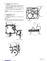
Page 58: ...rclockwise as you turn the flywheel R counterclockwise See Fig 2 and 3 3 Disconnect the flexible wire from connector CN31 on the head amplifier mechanism control board 4 Remove the spring from the back of the head 5 Loosen the azimuth screw for reversing attaching the head 6 Remove the head on the front side of the head mount Fig 1 Fig 2 Fig 3 Cassette mechanism assembly Fly wheelR Trigger arm Hea...

Page 59: ...l pulse board REFERENCE If necessary unsolder the 4 pin wire soldered to the main motor 3 5 3 Removing the main motor See Fig 4 7 1 Remove the two screws B 2 Half raise the motor and remove the capstan belt from the motor pulley ATTENTION Be careful to keep the capstan belt from grease When reas sembling refer to Fig 6 and 7 for attaching the capstan belt Fig 4 Fig 5 Fig 6 Fig 7 Head amplifier mec...

Page 60: ...rd Fig 8 Fig 9 3 5 5 Removing the reel pulse board and solenoid See Fig 10 Prior to performing the following procedure remove the head amplifier mechanism control board 1 Remove the screw C 2 Release the tab a b c d and e retaining the reel pulse board 3 Release the tab f and g attaching the solenoid on the reel pulse board 4 The reel pulse board and the solenoid come off Fig 10 Fly wheel R Fly wh...

Page 61: ...the left to disengage the gear If the gear can not be disengaged easily push up the boss Q slightly and raise the rear side of the head mounts slightly to return the direction lever to the reversing side 2 Tighten the azimuth screw for reversing 3 Reattach the spring from the back of the Play Record Clear head 4 Connect the flexible wire to connector CN31 on the head amplifier mechanism control bo...

Page 62: ...F system then AC ON again Remocon Key STANDBY ON ENTER 0 CLOCK FAST FORWARDING Fast Forward clock Increase clock counter speed Can only be activated after SYSTEM clock is set to exit this TEST mode AC OFF the system then AC ON again Remocon Key STANDBY ON ENTER 2 FAN ON OFF setting Toggle between FAN switch ON and OFF FAN CTL L H TOGGLE This test mode is only effective during STANDBY MODE Test mod...

Page 63: ...INFO After 5 seconds return to previous display STOP EJECT4 key a AC power off b Press and hold STOP DVD5 EJECT CLOSE keys c AC power On while holding STOP DVD5 EJECT CLOSE keys d DVD mecha will start in TEST MODE LCD will display xx is the received DESTINATION information Display as follows xx JC 1U D E 2U 3U UB UT 4U UY EE UF y region number v study state information from MECHA CON Display Byte3...

Page 64: ...j j j j Byte 0 0x00 Byte 7 0x00 Byte 5 6 DISPLAY Status 00 NORMAL XX XX cc cc jj jj D V D L L D R S 2 seconds Static c c c j c j j j cccc Byte 0 0x00 Byte 7 0x00 Byte 3 4 DISPLAY j j j j Byte 0 0x00 Byte 7 0x00 Byte 5 6 DISPLAY Status 00 NORMAL XX XX cc cc jj jj J I T X 1 2 seconds Static c c c j c j j j cccc Byte 0 0x00 Byte 7 0x00 Byte 3 4 DISPLAY j j j j Byte 0 0x00 Byte 7 0x00 Byte 5 6 DISPLAY...

Page 65: ... No MB531 1 65 SECTION 5 TROUBLESHOOTING This service manual does not describe TROUBLESHOOTING ...

Page 66: ... No MB531 Audio Video Systems Category 10 1 1chome Ohwatari machi Maebashi city 371 8543 Japan Victor Company of Japan Limited VPT Printed in Japan ...

Page 67: ...s Printed circuit boards 2 1 2 4 2 23 to 29 CD ROM No SML200606 COMPACT COMPONENT SYSTEM No MB531SCH 2006 6 COPYRIGHT 2006 Victor Company of Japan Limited Lead free solder used in the board material Sn Ag Cu melting point 219 Centigrade SUPER VIDEO CA DXT66 SP DXT99W SP DXT66F SP DXT66F CA DXT77 SP DXT77S SP DXT77S SP DXT99W SP DXT99F SP DXT99F SP DXT77C SUPER VIDEO CA DXT99 SP DXT99S SP DXT99S SP...

Page 68: ...ponent parts appearing on the silk screen printed side parts side of the PWB diagrams the parts that are printed over with black such as the resistor diode and ICP or identified by the mark nearby are critical for safety ...

Page 69: ... FL DRIVER FL500 FL P1 to P35 1G to 10G FL display section FL CON FL DATA FL CLK FL BK FL LATCH D5004 Q5004 RHYTHM AX LED LED RHY D5005 Q5005 KARAOKE SCORING LED LED KAOK D5006 Q5006 Q5010 PRESET LED LDE DIM LED ILLU S5000 to S5034 KEY MATRIX F KEY1 to F KEY4 FW500 CN105 FL1 FL2 CN100 AC INPUT S1000 VOLTAGE SELECTOR SWTCH CN101 CN102 T1001 TRANS CN103 CN106 S1 D1004 to D1011 VH BRIDGE Q1000 35V RE...

Page 70: ...500 FL DRIVER FL500 FL P1 to P35 1G to 10G FL display section FL CON FL DATA FL CLK FL BK FL LATCH D5004 Q5004 RHYTHM AX LED LED RHY D5005 Q5005 KARAOKE SCORING LED LED KAOK D5006 Q5006 Q5010 PRESET LED LDE DIM LED ILLU S5000 to S5034 KEY MATRIX F KEY1 to F KEY4 FW500 CN105 FL1 FL2 CN100 AC INPUT S1000 VOLTAGE SELECTOR SWTCH CN101 CN102 T1001 TRANS CN103 CN106 S1 D1004 to D1011 VH BRIDGE Q1000 35V...

Page 71: ...ck section CN48 FW100 CN1 CN41 CN45 VR37 VR37 CN46 CN47 CN33 CN34 CN730 CN720 CN500 IC510 REMOCON RECEIVER REM D5007 Q5009 STANDBY LED LED STBY IC500 FL DRIVER FL500 FL P1 to P35 1G to 10G FL display section FL CON FL DATA FL CLK FL BK FL LATCH D5004 Q5004 RHYTHM AX LED LED RHY D5005 Q5005 KARAOKE SCORING LED LED KAOK D5006 Q5006 Q5010 PRESET LED LDE DIM LED ILLU S5000 to S5034 KEY MATRIX F KEY1 t...

Page 72: ... C1015 R2001 C2004 R2009 R2010 R2008 R2007 R2004 C2010 C2011 D2009 QGA3901F1 03 100 50 T1 25AL 250V KTC3203 OY T QGD2504C1 03Z 1N4003S T5 QQT0477 003 QGB2510J1 20 QGA3901F1 08 10 50 1SS133 T2 1N4003S T5 T5AL 250V 0 1 0 1 470 470 T5AL 250V QGB2510J1 16 T5AL 250V T5AL 250V 27K QGB2510K2 15 GBU803 MTZJ6 2B T2 T3 15AL 250V 47 0 1 KTC2026 Y 0 1 250 NI T6 3AL 250V T6 3AL 250V T8AL 250V T6 3AL 250V 0 1 N...

Page 73: ... NI NI 0 1 JCV8011 X B W RC4558D X RC4558D X 68K 10K 22K M65851FP 2 2K 10K KTC3199 GL T 27K 100 RC4558D X 4 7K 820K 22K 10k 4 7 50 0 1 100 16 0 15 0 022 NI 2 2K QGF1205C2 08 KTC3199 GL T 1K NI NI 10K 10K 0 1K 1K 100 16 4 7K 4 7K 12K 3 3K 0 1 0 1 11K 10K 10K NI QGF1036C2 19 10 50 1 50 1K 1K 10K 10K LC75342M X LC75342M X 220K QUY150 050Y 0 1 50 1 50 2 7K 1K 10K 10K 1K 1N4003S T5 KRA102S X 2 2K 1K 2 ...

Page 74: ... Q4601 C3811 R3902 R3302 R3303 R4901 R4902 R4904 C4901 C4902 D4901 Q4902 R4610 R4710 R3304 R3305 D3303 D3304 D3901 Q3902 C3832 D3902 D3832 D3831 R3831 C3104 C3842 R4906 D3841 C3841 C4401 C3831 D3821 C3821 R3205 R3204 R3206 STK412 430 STK412 430 QGB2510K2 16 1K 220P 220P KIA7810API QGB2510K2 20 KTA1023 OY T KTC1027 OY T KTC3200 GL T 10K 10K 56K STK413 430 10 35 10 35 56K 10 50 1K 1K 1K 1K 56K KIA78...

Page 75: ... 390 390 130 390 820 4 7K 4 7K 470K QNS0266 001 130 390 430 1K 470 10 390 1K 0 NI 430 0 1 50 NI NI KTA1023 OY T 22 50 KTC3875 YG X PT6305 100K QQL231K 470Y QQL231K 470Y 2SD2114K VW X KTC3875 YG X KRC102M T KRC102M T 22 50 10K 100p 0 001 0 1 GP1UM281XKVF KRC102M T 2SD2114K VW X 2SD2114K VW X 2SD2114K VW X 4 7k 4 7k 4 7k 4 7k KRA111S X QGF1205F2 05 0 1 50 RC4580ID X NI MTZJ3 3B T2 MTZJ2 0A T2 1SS133...

Page 76: ...0 C1015 R2001 C2004 R2009 R2010 R2008 R2007 R2004 C2010 C2011 D2009 QGA3901F2 03 T1 25AL 250V KTC3203 OY T QGD2504C1 03Z QQT0476 001 QGB2510J1 20 QGA3901F1 08 10 50 1SS133 T2 T4AL 250V 0 1 0 1 470 470 T4AL 250V 27K T4AL 250V T4AL 250V 100 50 QGB2510J1 16 GBU803 1N4003S T5 1N4003S T5 MTZJ6 2B T2 T3 15AL 250V 47 0 1 QGB2510K2 13 KTC2026 Y 0 1 250 NI T6 3AL 250V T6 3AL 250V T6 3AL 250V T5AL 250V 0 1 ...

Page 77: ...I NI NI 0 1 JCV8011 X B W RC4558D X RC4558D X 68K 10K 22K M65851FP 2 2K 10K KTC3199 GL T 27K 100 RC4558D X 4 7K 820K 22K 10k 4 7 50 0 1 100 16 0 15 0 022 NI 2 2K QGF1205C2 08 KTC3199 GL T 1K NI NI 10K 10K 0 1K 1K 100 16 4 7K 4 7K 12K 3 3K 0 1 0 1 11K 10K 10K NI QGF1036C2 19 10 50 1 50 1K 1K 10K 10K LC75342M X LC75342M X 220K QUY150 050Y 0 1 50 1 50 2 7K 1K 10K 10K 1K 1N4003S T5 KRA102S X 2 2K 1K 2...

Page 78: ...12 C6701 C6702 D6701 Q6702 C6401 C6402 R6706 R6358 C6321 C6322 R6321 R6231 C6311 R6352 R6211 D6351 Q6352 C6342 D6352 D6342 D6341 R6342 C6005 C6362 D6361 C6361 C6341 D6331 C6331 R6112 R6132 R6122 QGF1205F2 11 KTA1023 OY T KTC1027 OY T KTC3200 GL T 10K 10K KIA7809API 56K STK402 240 STK413 430 100 50 100 MTZJ9 1B T2 56K NI 47 1K 47 10 50 100 50 KIA7808API 22P MTZJ9 1B T2 KIA278R09PI 100 KTC3199 GL T ...

Page 79: ...1 390 390 130 390 820 4 7K 4 7K 470K QNS0266 001 130 390 430 1K 470 10 390 1K 0 NI 430 0 1 50 NI NI KTA1023 OY T 22 50 KTC3875 YG X PT6305 100K QQL231K 470Y QQL231K 470Y 2SD2114K VW X KTC3875 YG X KRC102M T KRC102M T 22 50 10K 100p 0 001 0 1 GP1UM281XKVF KRC102M T 2SD2114K VW X 2SD2114K VW X 2SD2114K VW X 4 7k 4 7k 4 7k 4 7k KRA111S X QGF1205F2 05 0 1 50 RC4580ID X NI MTZJ3 3B T2 MTZJ2 0A T2 1SS13...

Page 80: ... R2003 C2008 R2000 C2000 C1015 R2001 C2004 R2009 R2010 R2008 R2007 R2004 C2010 C2011 D2009 0 1 QGA3901F2 03 0 1 NI T1 6AL 250V KTC3203 OY T QGD2504C1 03Z NI QQT0516 001 QGA3901F1 08 10 50 T8AL 250V 0 1 0 1 470 470 NI 27K T8AL 250V NI 100 100 NI CN203 QGB2510J1 13 1N4003S T5 1N4003S T5 MTZJ6 2B T2 T3 15AL 250V 47 QGB2510J1 09 1 1 KTC2026 Y 0 1 250 GBU803 T6 3AL 250V T6 3AL 250V T6 3AL 250V T3 15AL ...

Page 81: ...24K 100 RC4558D X QGF1210G1 06 4700P 9 1K 22K 10k 4 7 50 0 1 100 16 3300P 0 15 9 1K 0 0022 2 2K QGF1205C2 08 0 0022 1K 27k 10K 0 1K 1K 100 16 4 7K 0 47K 4 7K 12K 3 3K 0 1 0 1 11K 3 9K 4 7 10K 10K 3 9K QGF1036C2 19 QNN0792 001 10K 0 1 50 0 NI NI NI 47 25 10K 220K QUY150 050Y 10K 120K 120K 1K 1N4003S T5 KRA102S X 2 2K 1K 2 2K 2 2K 2 2K 2 2K 1K 1K 10K 2 2K 2 2K 2 2K 1K 1K 1K 2 2K 1K 10K 1K 150 150 15...

Page 82: ...L6511 C6361 C6341 D6331 C6331 R6806 R6531 R6802 R6803 R6804 R6805 D6803 D6804 C6604 R6701 R6702 R6704 R6922 R6912 C6701 C6702 D6701 Q6702 Q6703 Q6701 R6706 QGF1205F2 11 KIA7809API KIA7805API KTA1023 OY T KTC1027 OY T KTC3200 GL T 10K 10K 56K QGB2510K2 09 STK413 430 1K KIA7808API KIA278R09PI KIA7809API NI NI QGB2510K2 13 QGF1205C2 13 15 15 KIA278R05PI 10 50 22p NI KTC3199 GL T KTC3199 GL T 56K KIA7...

Page 83: ...1 390 390 130 390 820 4 7K 4 7K 470K QNS0266 001 130 390 430 1K 470 10 390 1K 0 NI 430 0 1 50 NI NI KTA1023 OY T 22 50 KTC3875 YG X PT6305 100K QQL231K 470Y QQL231K 470Y 2SD2114K VW X KTC3875 YG X KRC102M T KRC102M T 22 50 10K 100p 0 001 0 1 GP1UM281XKVF KRC102M T 2SD2114K VW X 2SD2114K VW X 2SD2114K VW X 4 7k 4 7k 4 7k 4 7k KRA111S X QGF1205F2 05 0 1 50 RC4580ID X NI MTZJ3 3B T2 MTZJ2 0A T2 1SS13...

Page 84: ...A0 242 MA6 243 MA1 244 MA5 245 MA2 246 MA4 247 MA3 248 VSS 249 VDD33 250 DQM2 251 DQM3 252 MDQ31 253 MDQ16 254 MDQ30 255 DQM17 256 DQM29 750 R350 0 1 C310 F 220p C202 TP315 1 C356 0 01 C393 220 R357 1k R385 1k R376 0 1 C309 F 0 R335 0 1 C204 F TP381 TP107 0 1 C323 TP334 TP331 NI C374 F TP116 1 C304 K352 NQR0502 001X IC201 LA6502 X 1 2 3 4 5 6 7 8 9 10 11 12 49 13 14 15 16 17 18 19 20 21 22 23 24 2...

Page 85: ...TP453 CN452 QGA2001F6 02X 1 2 CN453 QGA2001F6 03X 1 2 3 TP473 K455 0 IC451 MN101C61GNW 1 VREF 2 LSENSOR 3 DET3 3V 4 DET1 2V 5 6 7 SM1 SM2 8 OUTC 9 VPP 10 VREF 11 VDD 12 OSC2 13 OSC1 14 VSS 15 XI 16 XO 17 MMOD 18 DISPS2D 19 DISPD2S 20 DISPCK 21 S2UDT 22 U2SDT 23 UCLK 24 25 RESET 26 SCS 27 CPURST 28 DISPBUSY 29 30 31 UCS 32 DISPCS 33 INT 34 35 36 37 38 39 EPCS 40 EPSK 41 EPDI 42 EPDO 43 44 STSTSW 45...

Page 86: ...MCK 224 VDD33 225 MCKI 226 VSS 227 NCAS 228 NRAS 229 NCSM 230 MA11 231 BA0 232 MA9 233 VSS 234 VDD12 235 BA1 236 MA8 237 MA10 238 VSS 239 DVV33 240 MA7 241 MA0 242 MA6 243 MA1 244 MA5 245 MA2 246 MA4 247 MA3 248 VSS 249 VDD33 250 DQM2 251 DQM3 252 MDQ31 253 MDQ16 254 MDQ30 255 DQM17 256 DQM29 750 R350 0 1 C310 F 2 2 0 p C 2 0 2 TP315 1 C 3 5 6 0 0 1 C 3 9 3 2 2 0 R 3 5 7 1 k R 3 8 5 1k R376 0 1 C3...

Page 87: ...6F8 15W 1 2 3 4 5 6 7 8 9 10 11 12 13 14 15 TP459 B3 3V TP417 TP460 TP474 R463 100 TP453 CN452 QGA2001F6 02X 1 2 CN453 QGA2001F6 03X 1 2 3 TP473 K455 0 IC451 MN101C61GNW 1 VREF 2 LSENSOR 3 DET3 3V 4 DET1 2V 5 6 7 SM1 SM2 8 OUTC 9 VPP 10 VREF 11 VDD 12 OSC2 13 OSC1 14 VSS 15 XI 16 XO 17 MMOD 18 DISPS2D 19 DISPD2S 20 DISPCK 21 S2UDT 22 U2SDT 23 UCLK 24 25 RESET 26 SCS 27 CPURST 28 DISPBUSY 29 30 31 ...

Page 88: ...164 001 QSW0923 001 LB1641 LB1641 0 1 50 0 1 50 NI 0 1 50 MTZJ6 2A T2 QGB2024J1 07S QSW0844 001 QSW0844 001 QSW0844 001 QSW0844 001 QSW0844 001 QGB2024K1 07S 0 01 50 0 01 50 100 10 QGF1036F1 15 TR5_CL TR4_CL TR3_CL TR2_CL TR1_CL TR1_CL TR2_CL TR3_CL TR4_CL TR5_CL M TR_OP POS_UP TR_OP POS_DOWN TR_CL M TR_OP TR1_CL TR5_CL TR2_CL TR4_CL TR3_CL TR_OP TR1_CL TR2_CL TR3_CL TR4_CL TR5_CL TR_CL POS_DOWN P...

Page 89: ...TC3199 GL T KTA1271 OY T 100 MTZJ5 1B T2 QGF1205F1 09 100 100P 100P QGF1201F3 10 CD4094BC 100 10 100 10 2 2 50 390P 100 2 2 50 47K 47K 13K 100 10 2 2 50 12K QGF1210G1 10 NI QGF1210G1 09 2 2 50 NI 820P 820P 13K 4 7K QGF1205F1 09 QGF1205F1 09 4 7K 4 7K 47K NJM4565 QVP0077 103Z 4 7K 47K 390P 56K VKZ3174 00B 100 3 3K QGF1205F1 06 SG 105F3 1SS133 T2 2SC3576 JVC T 2SC3576 JVC T 220 3 3K 47 16 QGF1205F1 ...

Page 90: ...20 10k 11K QVP0008 203Z KTC3199 GL T KTA1271 OY T 100K MTZJ5 1B T QGF1205F1 09 NI MSI 5U2LWA 2 2K QGF1201F3 10 CD4094BC 10 330P 50 HA12238F 4 7 10K 10K 15K 15K KRC107M T 0 01 16 12K 9 1K 100 27K 2 2K QGF1205F1 09 QGF1205F1 09 QVP0077 103Z 330P 50 QQR1118 001 10 16 VKZ3174 00B 3 9K GP2S24CJ000F 9 1K 3 3K 270P 50 2SB562 C KRC107M T 0 01 16 22K 47 50 150P 50 1 50 47 50 150P 50 QAH0101 001 2SK2001 0 0...

Page 91: ... R7767 R7768 R7769 R7770 R7775 R7776 R7777 R777 8 R77 79 R7780 R7781 R7786 R7787 R7788 R7789 R7790 R7791 R7792 R7793 R7794 R7796 R7797 R7798 R7799 R7802 R7803 R7804 R7805 R7806 R7807 R7808 R7809 R7821 R7823 R7824 R7825 R7867 R7871 C8002 R7875 R7876 R7878 R7879 R7886 R7897 R7852 R7892 C7824 R8000 R8001 R8002 R8003 R8004 R8005 R8006 R8007 R8020 C7008 R8332 R8039 R8119 R7600 R8132 R8186 C8180 C8563 R...

Page 92: ... R8131 R7253 R7350 R7351 R8412 R8418 R7702 R7703 R7704 R7705 R7706 R7707 R7708 R7709 R7715 R7717 R7921 C7825 R7721 R7722 R7723 R7724 R8400 R7726 R7728 R7731 R7732 R7735 R7736 R7737 R7738 R7739 R7740 R7742 R7743 R7744 R7745 R7746 R7747 R7748 R7749 R7754 R7753 C8556 R7600 R7756 R7751 R7762 R7766 R8492 R8493 R7767 R7768 R7769 R7770 R7775 R7776 R7777 R7778 R7779 R7780 R7781 R7786 R7787 R7788 R7789 R77...

Page 93: ...04 C3605 C3702 C3202 C3832 C3212 C3812 C3222 C3822 HS301 C3842 CN303 CN304 D3101 D3301 D3302 D3303 D3304 D3401 D3501 D3601 D3701 D3811 D3821 D3831 D3832 D3841 D3901 D3902 IC301 IC302 IC303 IC304 IC305 IC306 IC307 L3401 L3501 L3601 Q3101 Q3102 Q3103 Q3104 Q3401 Q3501 Q3601 Q3901 Q3902 R3101 R3102 R3103 R3104 R3105 R3106 R3107 R3108 R3201 R3202 R3203 R3204 R3205 R3206 R3301 R3302 R3303 R3304 R3305 R...

Page 94: ...N604 D6001 D6002 D6211 D6221 D6231 D6311 D6321 D6331 D6341 D6342 D6361 D6353 D6352 IC601 IC602 IC603 IC604 IC605 IC606 IC607 L6211 L6221 L6231 Q6001 Q6002 Q6211 Q6221 Q6231 Q6351 Q6352 R6001 R6002 R6003 R6004 R6005 CN601 R6111 R6112 R6121 R6122 R6131 R6132 R6212 R6213 R6214 R6215 R6216 R6217 R6218 R6219 R6222 R6223 R6224 R6225 R6226 R6227 R6228 R6229 R6232 R6233 R6234 R6235 R6236 R6237 R6238 R6239...

Page 95: ... D1000 D1001 D1002 D1003 D1013 D1014 D1012 D1011 Z1001 Z1007 Z1009 Z1005 D1010 C1013 R1000 C1014 R1002 R1003 R1004 R1006 CN101 CN102 Z1002 Z1013 Z1011 Z1012 Z1006 Z1008 Z1010 EP101 CN103 D1009 D1008 Q1001 Z1015 Z1018 Z1019 Z1014 Z1016 Z1017 C1016 C1017 CN106 Z1020 Q1000 C1015 D1016 D1015 D1017 R1005 CN104 D1004 D1005 D1006 D1007 C9201 C9200 C9204 C9206 C9209 C9211 C9213 C9215 C9218 C9221 C9224 C92...

Page 96: ...5 K456 K721 K723 K724 K725 K726 K727 K728 K732 K733 K734 K735 TP309 K737 K738 K750 K752 K754 K756 K758 R301 Q101 Q102 Q103 Q104 R107 TP101 TP102 TP103 TP104 TP105 TP108 TP109 TP111 TP201 TP202 TP203 TP204 TP205 TP206 TP207 TP208 TP220 TP221 TP226 TP227 TP231 TP300 TP301 TP304 TP306 TP307 K710 TP314 TP315 TP320 TP321 TP323 TP324 TP325 TP326 TP328 TP329 TP330 TP331 TP332 TP333 TP334 TP335 TP338 TP38...

Page 97: ...rd Lead free solder used in the board material Sn Ag Cu melting point 219 Centigrade common D1 FW100 R371 VR37 P1 SW6 CN1 IC1 C201 C102 C103 C105 C106 C107 C209 C110 C113 C121 C101 C202 C203 C205 C206 C207 C109 C210 C213 C221 C300 C301 C304 C306 C307 C308 C310 C313 C314 C316 C319 C331 C340 C341 C342 C371 C374 C376 CN31 CN33 CN34 Q348 D375 IC32 IC33 L301 L303 Q302 Q305 Q342 Q343 Q344 Q345 Q346 Q371...

Page 98: ...Victor Company of Japan Limited No MB531SCH Printed in Japan VPT Audio Video Systems Category 10 1 1chome Ohwatari machi Maebashi city 371 8543 Japan ...

Page 99: ... Block No MP SLC S401M Cassette A Common Cassette mechanism assembly and parts list Block No MQ SLC S304M Cassette B Common Electrical parts list Block No 01 15 Packing materials and accessories parts list Block No M4 DX T99 Packing materials and accessories parts list Block No M5 DX T77 Packing materials and accessories parts list Block No M6 DX T66 DX T99A DX T99EE DX T99US DX T99UW 3 2 3 6 3 10...

Page 100: ... B D F F G G FL board DX T99 Cassette A Cassette B 20 13 14 38 21 12 20 1 47 47 2 3 49 49 4 42 40 41 45 44 17 15 55 17 39 43 46 39 36 11 10 16 31 19 23 94 94 94 94 94 94 22 24 24 22 23 62 57 8 7 16 16 34 37 33 32 36 38 37 33 34 50 51 35 32 56 51 50 31 28 21 35 9 6 5 48 48 121 111 96 123 t 54 54 125 98 97 97 99 26 ...

Page 101: ...e f a f e j g s t r s r p b p Cassette B A 16 31 48 68 16 16 16 57 57 16 16 31 28 48 29 63 58 66 66 18 70 18 60 59 69 71 63 60 59 65 61 74 73 72 82 92 88 85 92 81 84 85 93 85 90 91 79 95 83 78 80 67 77 76 28 30 64 63 8 53 52 53 52 48 106 105 104 103 107 101 102 109 110 108 86 89 87 113 111 112 119 117 118 122 116 120 114 115 100 75 25 99 124 27 26 ...

Page 102: ...W M3 x 8mm x2 36 QYSBSF3010ZA TAP SCREW M3 x 10mm x2 37 GV40503 001A WASHER x2 38 GV40504 002A SCREW x2 39 GV40515 001A METAL PIN x2 40 GV10262 002A CASS HOLDER A 41 GV10261 003A CASS HOLDER B 42 GV20344 001A CASS LENS A 43 GV20343 001A CASS LENS B 44 GV30705 001A LENS ORNAMENT 45 GV40596 001A DOOR SPRING B 46 GV40619 001A DOOR SPRING A 47 GV40034 001A DAMPER ASSY x2 48 QYSBSF3010ZA TAP SCREW M3 x...

Page 103: ...DER 97 GV30349 021A SPACER x2 98 GV30349 049A SPACER 99 GV40531 002A LED HOLDER 100 QQT0477 003 POWER TRANSF T1001 101 QMFZ051 8R0 J8 FUSE F1001 8A 102 QMF51W2 6R3 J8 FUSE F1002 6 3A AC250V 103 QMF51W2 6R3 J8 FUSE F1003 6 3A AC250V 104 QMF51W2 6R3 J8 FUSE F1004 6 3A AC250V 105 QMF51W2 1R25 J8 FUSE F1005 1 25A AC250V 106 QMF51W2 3R15 J8 FUSE F1006 3 15A AC250V 107 QMF51W2 5R0 J8 FUSE F1007 5A AC250...

Page 104: ... B D F F G G FL board DX T77 Cassette A Cassette B 20 13 14 38 21 12 20 1 47 47 2 3 49 49 4 42 40 41 45 44 17 15 55 17 39 43 46 39 36 11 10 16 31 19 23 94 94 94 94 94 94 22 24 24 22 23 62 57 8 7 16 16 34 37 33 32 36 38 37 33 34 50 51 35 32 56 51 50 31 28 21 35 9 6 5 48 48 121 111 96 123 t 54 54 126 98 97 97 99 26 ...

Page 105: ...a f e j g s t r s r p b p Cassette B A 16 31 48 68 16 16 16 57 57 16 16 31 28 48 29 63 58 66 66 18 70 18 60 59 69 71 63 60 59 65 61 74 73 72 82 92 88 85 92 81 84 85 93 85 90 91 79 95 83 78 80 67 76 77 28 30 64 63 8 53 52 53 52 48 106 105 104 103 107 101 102 109 110 108 86 89 87 113 111 112 119 117 118 122 116 120 114 115 100 75 25 99 125 27 26 127 124 ...

Page 106: ...TAP SCREW M3 x 8mm x2 36 QYSBSF3010ZA TAP SCREW M3 x 10mm x2 37 GV40503 001A WASHER x2 38 GV40504 002A SCREW x2 39 GV40515 001A METAL PIN x2 40 GV10262 002A CASS HOLDER A 41 GV10261 003A CASS HOLDER B 42 GV20344 001A CASS LENS A 43 GV20343 001A CASS LENS B 44 GV30705 001A LENS ORNAMENT 45 GV40596 001A DOOR SPRING B 46 GV40619 001A DOOR SPRING A 47 GV40034 001A DAMPER ASSY x2 48 QYSBSF3010ZA TAP SC...

Page 107: ... 99 GV40531 002A LED HOLDER 100 QQT0476 001 POWER TRANSF T1001 101 QMF51W2 6R3 J8 FUSE F1001 6 3A AC250V 102 QMF51W2 5R0 J8 FUSE F1002 5A AC250V 103 QMF51W2 6R3 J8 FUSE F1003 6 3A AC250V 104 QMF51W2 6R3 J8 FUSE F1004 6 3A AC250V 105 QMF51W2 1R25 J8 FUSE F1005 1 25A AC250V 106 QMF51W2 3R15 J8 FUSE F1006 3 15A AC250V 107 QMF51W2 4R0 J8 FUSE F1007 4A AC250V 108 QMF51W2 4R0 J8 FUSE F1008 4A AC250V 109...

Page 108: ... a B D F F G G FL board DX T66 Cassette A Cassette B 20 13 14 38 21 12 20 1 47 47 2 3 49 49 4 42 40 41 45 44 17 15 55 17 39 43 46 39 36 11 10 16 31 19 23 92 92 92 92 92 92 22 24 24 22 23 61 57 8 7 16 16 34 37 33 32 36 38 37 33 34 50 51 35 32 56 51 50 31 28 21 35 9 6 5 48 48 117 108 94 119 t 54 54 97 96 96 98 26 ...

Page 109: ... e j g s t r s r p b p Cassette B A 16 31 48 67 16 16 16 57 57 16 16 31 28 48 29 62 58 65 65 18 69 18 60 59 68 70 62 60 59 64 73 72 71 80 89 86 83 89 79 82 83 91 83 88 90 77 93 81 76 78 66 74 75 28 30 63 62 8 53 52 53 52 48 105 104 103 102 106 100 101 107 84 87 85 110 108 109 114 115 118 113 116 111 112 25 98 120 27 26 121 95 99 ...

Page 110: ...AP SCREW M3 x 8mm x2 36 QYSBSF3010ZA TAP SCREW M3 x 10mm x2 37 GV40503 001A WASHER x2 38 GV40504 002A SCREW x2 39 GV40515 001A METAL PIN x2 40 GV10262 002A CASS HOLDER A 41 GV10261 003A CASS HOLDER B 42 GV20344 001A CASS LENS A 43 GV20343 001A CASS LENS B 44 GV30705 003A LENS ORNAMENT 45 GV40596 001A DOOR SPRING B 46 GV40619 001A DOOR SPRING A 47 GV40034 001A DAMPER ASSY x2 48 QYSBSF3010ZA TAP SCR...

Page 111: ...GV40327 002A IC BRD HOLDER EP651 96 GV30349 021A SPACER x2 97 GV30349 049A SPACER 98 GV40531 002A LED HOLDER 99 QQT0516 001 POWER TRANSF T1001 100 QMF51W2 6R3 J8 FUSE F1001 6 3A AC250V 101 QMF51W2 3R15 J8 FUSE F1002 3 15A AC250V 102 QMF51W2 6R3 J8 FUSE F1003 6 3A AC250V 103 QMF51W2 6R3 J8 FUSE F1004 6 3A AC250V 104 QMF51W2 1R6 J8 FUSE F1005 1 6A AC250V 105 QMF51W2 3R15 J8 FUSE F1006 3 15A AC250V 1...

Page 112: ...ist Common Grease 1401C JVS 1003 JVG 31N Back side The parts without symbol number are not service FXL D20 11M 7 0mm 0 2mm Block No M M M J 19 32 26 31 21 16 17 32 32 24 23 25 30 29 27 28 18 20 3 15 13 1 6 14 7 22 9 11 10 8 32 4 5 2 31 3 12 ...

Page 113: ...25 0X5A SPACER 13 LV36557 001A F M GEAR 14 QYSPSPT2030MA SCREW M2 x 3mm 15 QYSDST2005ZA TAP SCREW M2 x 5mm 16 QAL0786 004 P UP 17 LV22237 001A RACK ARM 18 LV36560 001A RACK ARM SPRING 19 QYSPSFU1740ZA TAP SCREW M1 7 x 4mm x2 20 QUQK05 2415AC E FFC WIRE 24pin 15cm 21 LV44041 002A GUIDE SHAFT 22 LV36559 001A L S GEAR 23 LV41517 003A LEAD SCREW 24 LV36558 001A MIDDLE GEAR 25 LV36556 001A SPRING HOLDE...

Page 114: ... F FMU SB4 1M Block No M M M K d G C d B c cb e e a a G A E F CH5 BASE 1M The parts without symbol number are not service 6 5mm 0 1mm f f 37 36 45 35 8 13 27 29 22 21 23 6 7 1 23 26 9 25 10 27 11 2 3 31 33 34 12 16 20 20 17 14 32 30 40 40 43 28 4 38 5 5 4 24 4 39 41 39 39 42 43 44 44 43 18 19 15 20 ...

Page 115: ...LV43287 001A ELEVATOR SPRING 20 QYSDST2605Z SCREW 2 6mm x 5mm x3 21 LV10749 002A SIDE L 22 LV33980 001A OPEN DET LEVER 23 QYSDST2605Z SCREW 2 6mm x 5mm x2 24 LV10746 003A TRAY ASSY x5 25 LV10750 002A TOP COVER 26 LV43289 002A ROD x2 27 QYSDSF2608Z SCREW 2 6mm x 8mm x2 28 QYSDST2605Z SCREW 2 6mm x 5mm x2 29 QYSDSF2608Z SCREW 2 6mm x 8mm 30 QYSDST2605Z SCREW 2 6mm x 5mm 31 QYSDST2004Z SCREW 2mm x 4m...

Page 116: ...U SB4 11M Block No M M M S d G C d B c cb e e a a G A E F CH5 BASE 1M The parts without symbol number are not service 6 5mm 0 1mm f f 37 36 45 35 8 13 27 29 22 21 23 6 7 1 23 26 9 25 10 27 11 2 3 31 33 46 34 12 16 20 20 17 14 32 30 40 40 43 28 4 38 5 5 4 24 4 39 41 39 39 42 43 44 44 43 18 19 15 20 ...

Page 117: ...ZA TAP SCREW M2 6 x 5mm x3 21 LV10749 003A SIDE L 22 LV33980 002A OPEN DET LEVER 23 QYSDST2605ZA TAP SCREW M2 6 x 5mm x2 24 LV10746 007A TRAY ASSY x5 25 LV10750 002A TOP COVER 26 LV43289 003A ROD x2 27 QYSDSF2608ZA TAP SCREW M2 6 x 8mm x2 28 QYSDST2605ZA TAP SCREW M2 6 x 5mm x2 29 QYSDSF2608ZA TAP SCREW M2 6 x 8mm 30 QYSDST2605ZA TAP SCREW M2 6 x 5mm 31 QYSDST2004ZA TAP SCREW M2 x 4mm 32 WJM0330 0...

Page 118: ...MOBIL 1 1 27 13 3 34 2 8 15 10 14 16 7 12 23 3 2 4 9 6 5 24 29 25 22 17 20 19 18 11 21 31 36 26 28 30 1 11 6 5 33 32 33 32 35 35 SLC S401M A B 8 7 _ 0 1 0 15 mm A B C C Block No M M M P Grease The lower side Head amplifier board Switch board The parts without symbol number are not service ...

Page 119: ...D BASE SP L 14 LV41584 001A BRAKE R 15 LV41585 003A BRAKE L 16 LV44098 001A SPECIAL SCREW 17 VKS5603 00H MAIN PULLEY ASS 18 VKS3785 001MM FR ARM 19 VKW5284 002 SWING SPRING 20 VKS2278 003 TRIGGER ARM 21 VKW5301 001 FR SPRING 22 VKW5266 001 ELEVATOR SPRING 23 WDL214025 WASHER 24 QYSBSF2005ZA TAP SCREW M2 x 5mm 25 VKS3786 00G CLUTCH ASSY 26 VKF3205 00B F WHEEL ASSY R 27 WDL183425 SLIT WASHER 28 VKF3...

Page 120: ...MOBIL 1 1 29 13 3 34 2 8 15 10 14 16 7 12 23 3 2 4 9 5 6 24 27 25 22 17 20 19 18 11 21 31 36 26 28 30 1 11 5 6 33 32 33 32 35 35 SLC S304M A B 8 7 _ 0 1 0 15 mm A B C C Block No M M M Q Grease The lower side Head amplifier board Switch board The parts without symbol number are not service ...

Page 121: ... LV41585 003A BRAKE L 16 LV44098 001A SPECIAL SCREW 17 VKS5603 00H MAIN PULLEY ASS 18 VKS3785 001MM FR ARM 19 VKW5284 002 SWING SPRING 20 VKS2278 003 TRIGGER ARM 21 VKW5301 001 FR SPRING 22 VKW5266 001 ELEVATOR SPRING 23 QYWDL2140352 SLIT WASHER 4mm 2 1mm x 0 35mm 24 QYSBSF2005ZA TAP SCREW M2 x 5mm 25 VKS3786 00G CLUTCH ASSY 26 VKF3205 00B F WHEEL ASSY R 27 QYWDL183425 SLIT WASHER 3 4mm 1 8mm x 0 ...

Page 122: ...7710 QCBB1HK 103Y C CAPACITOR 0 01uF 50V K C7711 QETN1CM 107Z E CAPACITOR 100uF 16V M C7712 NCS31HJ 200X C CAPACITOR 20pF 50V J C7713 NCS31HJ 180X C CAPACITOR 18pF 50V J C7788 QETN1HM 106Z E CAPACITOR 10uF 50V M C7794 QETN1HM 106Z E CAPACITOR 10uF 50V M C7798 QETN1CM 107Z E CAPACITOR 100uF 16V M C8000 QTE1V06 106Z E CAPACITOR 10uF 35V C8001 QTE1V06 106Z E CAPACITOR 10uF 35V C8002 QTE1V06 106Z E CA...

Page 123: ...APACITOR 2200pF 50V K C9001 QETN1HM 104Z E CAPACITOR 0 1uF 50V M C9003 QEKC1EM 106Z E CAPACITOR 10uF 25V M Symbol No Part No Part Name Description Local C9004 QEKC1HM 474Z E CAPACITOR 0 47uF 50V M C9005 QEKC1HM 104Z E CAPACITOR 0 1uF 50V M C9006 QETN1HM 105Z E CAPACITOR 1uF 50V M C9007 QEKC1HM 104Z E CAPACITOR 0 1uF 50V M C9008 QETN1HM 105Z E CAPACITOR 1uF 50V M C9009 QETN1EM 476Z E CAPACITOR 47uF...

Page 124: ... RESISTOR 100kΩ 1 16W J Symbol No Part No Part Name Description Local R7875 NRSA63J 104X MG RESISTOR 100kΩ 1 16W J R7876 NRSA63J 103X MG RESISTOR 10kΩ 1 16W J R7878 NRSA63J 104X MG RESISTOR 100kΩ 1 16W J R7879 NRSA63J 103X MG RESISTOR 10kΩ 1 16W J R7881 QRE141J 103Y C RESISTOR 10kΩ 1 4W J R7886 NRSA63J 103X MG RESISTOR 10kΩ 1 16W J R7892 NRSA63J 103X MG RESISTOR 10kΩ 1 16W J R7897 NRSA63J 103X MG ...

Page 125: ...R8521 QRE141J 243Y C RESISTOR 24kΩ 1 4W J R8523 QRZ9006 4R7X FUSI RESISTOR 4 7Ω R8524 QRE141J 561Y C RESISTOR 560Ω 1 4W J R8529 NRSA63J 113X MG RESISTOR 11kΩ 1 16W J R8539 QRE141J 822Y C RESISTOR 8 2kΩ 1 4W J R8551 NRSA63J 223X MG RESISTOR 22kΩ 1 16W J R8574 NRSA63J 223X MG RESISTOR 22kΩ 1 16W J R8575 NRSA63J 223X MG RESISTOR 22kΩ 1 16W J R8578 QRE141J 681Y C RESISTOR 680Ω 1 4W J R8579 QRE141J 103...

Page 126: ... QFLC1HJ 104Z M CAPACITOR 0 1uF 50V J C3502 QCSB1HJ 150Y C CAPACITOR 15pF 50V J C3503 QETN1JM 476Z E CAPACITOR 47uF 63V M C3504 QFLC1HJ 104Z M CAPACITOR 0 1uF 50V J C3505 QFLC1HJ 104Z M CAPACITOR 0 1uF 50V J C3602 QCSB1HJ 150Y C CAPACITOR 15pF 50V J C3603 QETN1JM 476Z E CAPACITOR 47uF 63V M C3604 QFLC1HJ 104Z M CAPACITOR 0 1uF 50V J C3605 QFLC1HJ 104Z M CAPACITOR 0 1uF 50V J C3701 QETN1EM 476Z E C...

Page 127: ...kΩ 1 4W J R4203 QRJ146J 100X UNF C RESISTOR 10Ω 1 4W J Symbol No Part No Part Name Description Local R4204 QRJ146J 100X UNF C RESISTOR 10Ω 1 4W J R4205 QRE141J 102Y C RESISTOR 1kΩ 1 4W J R4206 QRE141J 202Y C RESISTOR 2kΩ 1 4W J R4207 QRE141J 473Y C RESISTOR 47kΩ 1 4W J R4208 QRE141J 562Y C RESISTOR 5 6kΩ 1 4W J R4209 QRJ146J 681X UNF C RESISTOR 680Ω 1 4W J R4210 QRE141J 104Y C RESISTOR 100kΩ 1 4W ...

Page 128: ...01Z PUSH SW I M S5021 QSW0683 001Z PUSH SW I M S5022 QSW0683 001Z PUSH SW I M S5023 QSW0683 001Z PUSH SW I M S5024 QSW0683 001Z PUSH SW I M S5025 QSW0683 001Z PUSH SW I M S5026 QSW0683 001Z PUSH SW I M S5027 QSW0683 001Z PUSH SW I M S5028 QSW0683 001Z PUSH SW I M S5029 QSW0683 001Z PUSH SW I M S5030 QSW0683 001Z PUSH SW I M S5031 QSW0683 001Z PUSH SW I M S5032 QSW0683 001Z PUSH SW I M Symbol No Pa...

Page 129: ... 04 CONNECTOR W B 1 4 CN102 QGA7901C1 03 CONNECTOR W B 1 3 CN103 QGA3901F1 08 CONNECTOR W B 1 8 CN104 QGB2510J1 13 CONNECTOR B B 1 13 CN105 QGD2503F1 03 CONNECTOR 1 3 CN106 QGA3901F2 03 CONNECTOR W B 1 3 CN200 QGB2510J1 16 CONNECTOR B B 1 16 CN201 QGB2510J1 20 CONNECTOR B B 1 20 CN202 QGD2504C1 03Z CONNECTOR 1 3 CN203 QGB2510K2 15 CONNECTOR B B 1 15 CN204 QGB2510K2 13 CONNECTOR B B 1 13 CN920 QGF1...

Page 130: ...6Z E CAPACITOR 10uF 50V C8126 QFG32AJ 272Z PP CAPACITOR 2700pF 100V J C8127 QFLC1HJ 104Z M CAPACITOR 0 1uF 50V J C8128 QFLC1HJ 104Z M CAPACITOR 0 1uF 50V J C8130 QFLC1HJ 104Z M CAPACITOR 0 1uF 50V J C8131 QFLC1HJ 104Z M CAPACITOR 0 1uF 50V J C8132 QTE1C06 226Z E CAPACITOR 22uF 16V C8160 QTE1H28 106Z E CAPACITOR 10uF 50V C8161 QTE1H28 106Z E CAPACITOR 10uF 50V C8162 QTE1V06 106Z E CAPACITOR 10uF 35...

Page 131: ...t Name Description Local R7703 NRSA63J 102X MG RESISTOR 1kΩ 1 16W J R7704 NRSA63J 102X MG RESISTOR 1kΩ 1 16W J R7705 NRSA63J 102X MG RESISTOR 1kΩ 1 16W J R7706 NRSA63J 102X MG RESISTOR 1kΩ 1 16W J R7707 NRSA63J 222X MG RESISTOR 2 2kΩ 1 16W J R7708 NRSA63J 222X MG RESISTOR 2 2kΩ 1 16W J R7709 NRSA63J 222X MG RESISTOR 2 2kΩ 1 16W J R7715 NRSA63J 103X MG RESISTOR 10kΩ 1 16W J R7717 NRSA63J 103X MG RE...

Page 132: ...Ω 1 4W J Symbol No Part No Part Name Description Local R8130 QRE141J 472Y C RESISTOR 4 7kΩ 1 4W J R8131 QRE141J 332Y C RESISTOR 3 3kΩ 1 4W J R8132 QRE141J 682Y C RESISTOR 6 8kΩ 1 4W J R8133 QRE141J 124Y C RESISTOR 120kΩ 1 4W J R8134 QRE141J 473Y C RESISTOR 47kΩ 1 4W J R8135 NRSA63J 101X MG RESISTOR 100Ω 1 16W J R8136 NRSA63J 101X MG RESISTOR 100Ω 1 16W J R8142 QRE141J 392Y C RESISTOR 3 9kΩ 1 4W J ...

Page 133: ...CN830 QGF1205C2 19 CONNECTOR FFC FPC 1 19 CN850 QGB2510J1 13 CONNECTOR B B 1 13 CN860 QGB2510K2 04 CONNECTOR B B 1 4 CN901 QGF1205F2 05 CONNECTOR FFC FPC 1 5 FW910 QUM153 21DGZ4 E FLAT WIRE J700 QNB0300 002 SPK TERMINAL J800 QNN0420 001 SURROUND JACK J901 QNS0252 001 MIC JACK J902 QNS0252 001 MIC JACK J910 QNS0266 001 JACK K8000 NRSA63J 0R0X MG RESISTOR 0Ω 1 16W J K8001 NRSA63J 0R0X MG RESISTOR 0Ω...

Page 134: ...Y C RESISTOR 10kΩ 1 4W J Symbol No Part No Part Name Description Local R5009 QRE141J 102Y C RESISTOR 1kΩ 1 4W J R5010 QRE141J 102Y C RESISTOR 1kΩ 1 4W J R5011 QRE141J 122Y C RESISTOR 1 2kΩ 1 4W J R5012 QRE141J 182Y C RESISTOR 1 8kΩ 1 4W J R5013 QRE141J 222Y C RESISTOR 2 2kΩ 1 4W J R5014 QRE141J 272Y C RESISTOR 2 7kΩ 1 4W J R5015 QRE141J 392Y C RESISTOR 3 9kΩ 1 4W J R5016 QRE141J 102Y C RESISTOR 1k...

Page 135: ...OR 1kΩ 1 4W J R6922 QRE141J 563Y C RESISTOR 56kΩ 1 4W J R6931 QRE141J 102Y C RESISTOR 1kΩ 1 4W J R6932 QRE141J 563Y C RESISTOR 56kΩ 1 4W J L6211 QQLZ035 R39 COIL 0 39uH L6221 QQLZ035 R39 COIL 0 39uH L6231 QQLZ035 R39 COIL 0 39uH L6511 QQLZ035 R39 COIL 0 39uH L6521 QQLZ035 R39 COIL 0 39uH L6531 QQLZ035 R39 COIL 0 39uH CN500 QGF1036F2 19 CONNECTOR FFC FPC 1 19 CN601 QGB2510K2 20 CONNECTOR B B 1 20 C...

Page 136: ...J R2011 QRL01DJ 471X OMF RESISTOR 470Ω 1W J R2012 QRL01DJ 471X OMF RESISTOR 470Ω 1W J R2013 QRE141J 273Y C RESISTOR 27kΩ 1 4W J R9201 QRE141J 431Y C RESISTOR 430Ω 1 4W J R9202 QRE141J 391Y C RESISTOR 390Ω 1 4W J R9203 QRE141J 391Y C RESISTOR 390Ω 1 4W J R9204 QRE141J 131Y C RESISTOR 130Ω 1 4W J R9205 QRE141J 391Y C RESISTOR 390Ω 1 4W J R9206 QRE141J 131Y C RESISTOR 130Ω 1 4W J R9207 QRE141J 391Y C...

Page 137: ...1 QETN1HM 475Z E CAPACITOR 4 7uF 50V M C8122 QETN1HM 475Z E CAPACITOR 4 7uF 50V M C8123 QETN1HM 475Z E CAPACITOR 4 7uF 50V M C8125 QTE1H28 106Z E CAPACITOR 10uF 50V C8126 QFG32AJ 272Z PP CAPACITOR 2700pF 100V J C8127 QFLC1HJ 104Z M CAPACITOR 0 1uF 50V J C8128 QFLC1HJ 104Z M CAPACITOR 0 1uF 50V J C8130 QFLC1HJ 104Z M CAPACITOR 0 1uF 50V J C8131 QFLC1HJ 104Z M CAPACITOR 0 1uF 50V J C8132 QTE1H28 106...

Page 138: ...kΩ 1 16W J R7735 NRSA63J 102X MG RESISTOR 1kΩ 1 16W J Symbol No Part No Part Name Description Local R7737 NRSA63J 102X MG RESISTOR 1kΩ 1 16W J R7738 NRSA63J 102X MG RESISTOR 1kΩ 1 16W J R7739 NRSA63J 102X MG RESISTOR 1kΩ 1 16W J R7740 NRSA63J 102X MG RESISTOR 1kΩ 1 16W J R7742 NRSA63J 102X MG RESISTOR 1kΩ 1 16W J R7743 NRSA63J 102X MG RESISTOR 1kΩ 1 16W J R7744 NRSA63J 102X MG RESISTOR 1kΩ 1 16W J...

Page 139: ... MG RESISTOR 15kΩ 1 16W J R8265 NRSA63J 562X MG RESISTOR 5 6kΩ 1 16W J R8266 NRSA63J 472X MG RESISTOR 4 7kΩ 1 16W J Symbol No Part No Part Name Description Local R8267 NRSA63J 104X MG RESISTOR 100kΩ 1 16W J R8268 NRSA63J 622X MG RESISTOR 6 2kΩ 1 16W J R8269 QRE141J 222Y C RESISTOR 2 2kΩ 1 4W J R8293 QRE141J 393Y C RESISTOR 39kΩ 1 4W J R8335 QRE141J 224Y C RESISTOR 220kΩ 1 4W J R8401 QRE141J 472Y C...

Page 140: ...K C5008 QCBB1HK 103Y C CAPACITOR 0 01uF 50V K C6311 QETN1EM 476Z E CAPACITOR 47uF 25V M C6312 QETN1CM 107Z E CAPACITOR 100uF 16V M C6321 QETN1EM 476Z E CAPACITOR 47uF 25V M C6322 QETN1CM 107Z E CAPACITOR 100uF 16V M C6331 QETN1EM 476Z E CAPACITOR 47uF 25V M C6332 QETN1CM 107Z E CAPACITOR 100uF 16V M C6341 QETN1EM 476Z E CAPACITOR 47uF 25V M C6342 QETN1CM 107Z E CAPACITOR 100uF 16V M C6361 QETN1EM ...

Page 141: ... 10kΩ 1 4W J R6607 QRE141J 103Y C RESISTOR 10kΩ 1 4W J R6608 QRJ146J 150X UNF C RESISTOR 15Ω 1 4W J R6701 QRE141J 103Y C RESISTOR 10kΩ 1 4W J R6702 QRE141J 104Y C RESISTOR 100kΩ 1 4W J R6703 QRE141J 103Y C RESISTOR 10kΩ 1 4W J R6704 QRE141J 104Y C RESISTOR 100kΩ 1 4W J R6705 QRE141J 103Y C RESISTOR 10kΩ 1 4W J R6706 QRE141J 104Y C RESISTOR 100kΩ 1 4W J R6801 QRE141J 682Y C RESISTOR 6 8kΩ 1 4W J R6...

Page 142: ...K J921 QNN0557 002 PIN JACK PP201 QZW0112 001 WIRE CLAMP PP202 QZW0112 001 WIRE CLAMP Q1000 KTC2026 Y TRANSISTOR Q1001 KTC3203 OY T TRANSISTOR Symbol No Part No Part Name Description Local Q2007 KTA1046 Y TRANSISTOR Q2008 KTC3199 GL T TRANSISTOR Q2009 KTC3199 GL T TRANSISTOR Q9300 KRA110M T TRANSISTOR Q9301 KRC110M T TRANSISTOR Q9303 KTC3199 GL T TRANSISTOR R1000 QRK126J 470X UNF C RESISTOR 47Ω 1 ...

Page 143: ...25V Z C330 NCF31EZ 104X C CAPACITOR 0 1uF 25V Z C331 NCB31CK 333X C CAPACITOR 0 033uF 16V K C332 NCF31EZ 104X C CAPACITOR 0 1uF 25V Z C333 NCF31EZ 104X C CAPACITOR 0 1uF 25V Z C334 NCF31EZ 104X C CAPACITOR 0 1uF 25V Z C335 NCF31EZ 104X C CAPACITOR 0 1uF 25V Z C337 NCB31CK 183X C CAPACITOR 0 018uF 16V K C338 NCB31HK 562X C CAPACITOR 5600pF 50V K C339 NBE20JM 106X TA E CAPACITOR 10uF 6 3V M C340 NCB...

Page 144: ...RSA63J 102X MG RESISTOR 1kΩ 1 16W J R377 NRSA63J 102X MG RESISTOR 1kΩ 1 16W J R378 NRSA63J 102X MG RESISTOR 1kΩ 1 16W J R383 NRSA63J 101X MG RESISTOR 100Ω 1 16W J R384 NRSA63J 102X MG RESISTOR 1kΩ 1 16W J R385 NRSA63J 102X MG RESISTOR 1kΩ 1 16W J R392 NRSA63J 103X MG RESISTOR 10kΩ 1 16W J R452 NRSA63J 222X MG RESISTOR 2 2kΩ 1 16W J R453 NRSA63J 103X MG RESISTOR 10kΩ 1 16W J R454 NRSA63J 103X MG RE...

Page 145: ... Z C310 NCB31CK 104X C CAPACITOR 0 1uF 16V K C312 NCF31EZ 104X C CAPACITOR 0 1uF 25V Z C313 NCF31EZ 104X C CAPACITOR 0 1uF 25V Z C314 NCF31EZ 104X C CAPACITOR 0 1uF 25V Z C315 NCF31EZ 104X C CAPACITOR 0 1uF 25V Z C316 NCF31EZ 104X C CAPACITOR 0 1uF 25V Z C318 NCF31EZ 104X C CAPACITOR 0 1uF 25V Z C319 NCF31EZ 104X C CAPACITOR 0 1uF 25V Z C320 NCB31CK 104X C CAPACITOR 0 1uF 16V K C321 NCB31CK 104X C...

Page 146: ...0Ω 1 16W J R358 NRSA63J 221X MG RESISTOR 220Ω 1 16W J R362 NRSA63J 470X MG RESISTOR 47Ω 1 16W J R367 NRSA63J 221X MG RESISTOR 220Ω 1 16W J R372 NRSA63J 103X MG RESISTOR 10kΩ 1 16W J R373 NRSA63J 103X MG RESISTOR 10kΩ 1 16W J R375 NRSA63J 102X MG RESISTOR 1kΩ 1 16W J R376 NRSA63J 102X MG RESISTOR 1kΩ 1 16W J R377 NRSA63J 102X MG RESISTOR 1kΩ 1 16W J R378 NRSA63J 102X MG RESISTOR 1kΩ 1 16W J R383 NR...

Page 147: ...473Y C RESISTOR 47kΩ 1 4W J R467 QRE141J 473Y C RESISTOR 47kΩ 1 4W J R468 QRE141J 472Y C RESISTOR 4 7kΩ 1 4W J Symbol No Part No Part Name Description Local R469 QRE141J 472Y C RESISTOR 4 7kΩ 1 4W J R470 QRE141J 472Y C RESISTOR 4 7kΩ 1 4W J R471 QRE141J 473Y C RESISTOR 47kΩ 1 4W J R480 QRE141J 123Y C RESISTOR 12kΩ 1 4W J R481 QRE141J 183Y C RESISTOR 18kΩ 1 4W J R482 QRE141J 102Y C RESISTOR 1kΩ 1 4...

Page 148: ...C RESISTOR 1kΩ 1 4W J R221 QRE141J 153Y C RESISTOR 15kΩ 1 4W J R301 QRE141J 221Y C RESISTOR 220Ω 1 4W J R302 QRE141J 222Y C RESISTOR 2 2kΩ 1 4W J R303 QRE141J 222Y C RESISTOR 2 2kΩ 1 4W J R304 QRJ146J 101X UNF C RESISTOR 100Ω 1 4W J R305 QRE141J 103Y C RESISTOR 10kΩ 1 4W J R306 QRE141J 472Y C RESISTOR 4 7kΩ 1 4W J R310 QRJ146J 4R7X UNF C RESISTOR 4 7Ω 1 4W J R313 QRE141J 2R2Y C RESISTOR 2 2Ω 1 4W ...

Page 149: ...3 51 MEMO ...

Page 150: ...M 4 DX T99 No additional supplemental order of WARRANTY CARDs are available A1 A2 A3 A4 A5 A6 A7 A8 A11 P7 P4 P3 P2 P6 P5 A13 P1 A14 A9 A16 A20 A19 A18 P14A16 P15 A17 P10 P18 A18 P13 A15 P9 P8 P11 A22 P12 P12 P17 P17 P16 P16 P16 A19 A15 A21 A21 A17 P16 P15 A17 A12 ...

Page 151: ... T99EE T99US T99UX T99UG A 18 ASL8WXT99 EB20 SPEAKER BOX SUBWOOFER x2 T99UN A 18 ASL8WXT99 EB30 SPEAKER BOX SUBWOOFER x2 T99UW A 19 DUF803001 0001 LEG CUSHION x16 A 20 DUF803001 0002 LEG CUSHION x3 A 21 DUF803001 0003 LEG CUSHION x8 A 22 YOM800001 0273 USER MANUAL ENG ARA PER CHI T99A T99US T99UX T99UG T99UN A 22 YOM800001 0274 USER MANUAL ENG SPA POR T99UW A 22 YOM800001 0275 USER MANUAL RUS T99E...

Page 152: ...lock No M M M 5 DX T77 No additional supplemental order of WARRANTY CARDs are available A1 A2 A3 A4 A5 A6 A7 A8 A11 P7 P4 P3 P2 P6 P5 A12 P1 A13 A9 P8 A20 P13 P14 A14 P9 P13 P11 P10 P12 P16 P17 A17 P15 A16 P15 P15 A16 A15 A15 A16 A19 A19 A14 A18 A18 A17 ...

Page 153: ...ER T77EE T77US T77UX T77UG A 17 ASL8WXT99 EB30 SPEAKER BOX SUBWOOFER T77UW T77UY A 17 ASL8WXT99 EB20 SPEAKER BOX SUBWOOFER T77UN A 18 DUF803001 0001 LEG CUSHION x12 A 19 DUF803001 0002 LEG CUSHION x9 A 20 YOM800001 0270 USER MANUAL ENG ARA PER CHI T77US T77UX T77UG T77UN A 20 YOM800001 0272 USER MANUAL RUS T77EE A 20 YOM800001 0271 USER MANUAL ENG SPA POR T77UW T77UY P 1 GV20422 004A CARTON ASSY T...

Page 154: ...ssories parts list Block No M M M 6 DX T66 No additional supplemental order of WARRANTY CARDs are available A1 A2 A3 A4 A5 A6 A7 A8 A10 P1 P2 A9 P9 P3 P4 A11 P8 A12 P10 P12 P12 A13 A13 A14 P11 P11 P14 P13 P16 A15 A16 P15 P15 P5 P7 P6 ...

Page 155: ...1 GVT0184 001A VOL SEL SHEET T66UN A 12 GV40641 002A NOM LABEL T66UW A 13 ASL8MXT66 EB10 SPEAKER BOX MAIN SPK x2 A 14 DUF803001 0001 LEG CUSHION x8 A 15 GV30911 001A SPEAKER BOX SUBWOOFER A 16 DUF803001 0001 LEG CUSHION x4 P 1 GV20423 008A CARTON ASSY T66EE P 1 GV20423 007A CARTON ASSY T66US T66UN P 1 GV20423 006A CARTON ASSY T66UW T66UY P 1 GV20423 005A CARTON ASSY T66UX T66UG P 2 GV10339 002A CU...

Reviews: