


Masterpage:Right+
EN
11
Filename [MH200SEU_05Name.fm]
INDEX
Page 11
Wednesday, 25 May 2005 13:34
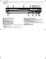
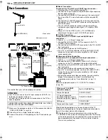
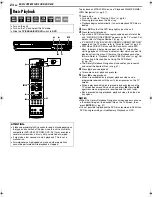
Rear View
A
Antenna Input Connector [ANTENNA IN]
A
pg. 16
B
Component Video Output Connectors [COMPONENT
VIDEO OUT (Y/P
B
/P
R
)]
A
pg. 16
C
S-video Output Connector [S-VIDEO]
A
pg. 16
D
Audio Output Connectors [AUDIO OUT (RIGHT/LEFT)]
A
pg. 61, 69
E
AV COMPU LINK Connector*
* Not function with this unit.
F
Digital Audio Output Connectors
[DIGITAL AUDIO OUT (OPTICAL/COAXIAL)]
A
pg. 61, 69
G
Cooling Fan
●
This prevents the temperature from rising inside the unit.
Do not remove it.
●
Install the unit so as not to block the area around the fan.
●
The unit may become hot when it is turned off, as the cooling
fan on the rear of the unit is not activated. However, the cooling
fan may be activated in the following cases;
^
In the Automatic Satellite Programme Recording standby
mode (
A
pg. 49), slightly before the starting time of VPS/PDC
recording (
A
pg. 46).
^
If you connect the decoder or satellite receiver to [L-2 IN/
DECODER], and if
A
L-2 SELECT
B
is set to
A
DECODER
B
,
A
SAT VIDEO
B
or
A
SAT S-VIDEO
B
. (
A
pg. 65)
^
When
A
JUST CLOCK
B
is set to
A
ON
B
(
A
pg. 77).
(Set
A
JUST CLOCK
B
to
A
OFF
B
if you mind the noise of the fan.)
H
AC Power Cord
A
pg. 16
I
Antenna Output Connector [ANTENNA OUT]
A
pg. 16
J
L-1 Input/Output Connector [L-1 IN/OUT]
A
pg. 16, 63, 68,
69
K
L-2 Input/Decoder Connector [L-2 IN/DECODER]
A
pg. 22,
63, 68, 69
L
Satellite Control Connector [SAT CONTROL]
A
pg. 22
M
Region Number Label
A
pg. 6
C
D
F
E
G
H
B
A
K
L
M
I
J
MH200SEU_00.book Page 11 Wednesday, May 25, 2005 1:34 PM


