background image

24 

EN

MasterPage: Heading0_Left

EDITING 

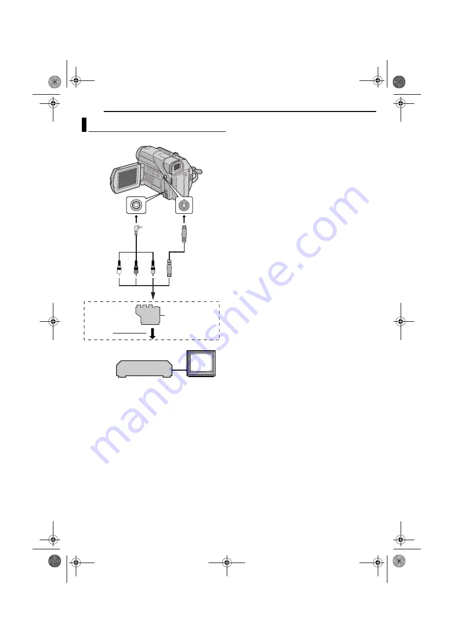
A

White to AUDIO L IN

B

Red to AUDIO R IN

C

Yellow to VIDEO IN

D

To S-VIDEO IN**

*

If your VCR has a SCART connector, use the provided 
cable adapter.

** Connect when your TV/VCR has an S-VIDEO IN 

connector. In this case, it is not necessary to connect the 
yellow video cable.

NOTE:

Set the video out select switch of the cable adapter as 
required:

Y/C: 

When connecting to a TV or VCR which accepts Y/

C signals and uses an S-Video cable.

CVBS: 

When connecting to a TV or VCR which does not 

accept Y/C signals and uses an audio/video cable.

To use this camcorder as a player

1

Following the illustrations, connect the camcorder and 

the VCR. Also refer to page 13.

2

Set the camcorder’s Power Switch to “PLAY” while 

pressing down the Lock Button located on the switch.

3

Turn on the VCR’s power.

4

Insert the source cassette in the camcorder.

5

Insert the recording cassette in the VCR.

6

Engage the VCR’s AUX and Record-Pause modes.

Refer to the instruction manual for the VCR.

7

Press 

4

/

9

 on the camcorder to start playback of the 

source tape.

8

At the point you want to start dubbing, engage the 

VCR’s Record mode.

9

To pause dubbing, engage the VCR’s Record-Pause 

mode and press 

4

/

9

 on the camcorder.

10

Repeat steps 

7

9

 for additional editing. Stop the 

VCR and camcorder.

NOTES:

It is recommended to use the AC Adapter as the power 
supply instead of the battery pack. (

pg. 7)

As the camcorder starts to play your footage, it will appear 
on your TV. This will confirm the connections and the AUX 
channel for dubbing purposes.

Before you start dubbing, make sure that the indications do 
not appear on the connected TV. If they do, they are being 
recorded onto the new tape.

To choose whether or not the following displays appear 
on the connected TV

• Date/time

Set “DATE/TIME” to “AUTO”, “ON” or “OFF”. 
(

pg. 14, 17)

• Time code

Set “TIME CODE” to “OFF” or “ON”. (

pg. 14, 17)

• Indications other than date/time and time code

Set “ON SCREEN” to “OFF”, “LCD” or “LCD/TV”. 
(

pg. 14, 17)

Dubbing To A VCR

1

2

3

4

TV

VCR

Audio/Video

cable

(provided)

To AV

To S

S-Video cable
(optional)

To TV or VCR

“Y/C”/“CVBS” Video 
Out Select Switch

Cable Adapter*

GR-D33EK_07Advanced.fm  Page 24  Friday, October 31, 2003  6:43 PM

Summary of Contents for Digital Video Camera GR-D24

Page 1: ... GETTING STARTED 5 VIDEO RECORDING PLAYBACK 10 ADVANCED FEATURES 14 REFERENCES 27 TERMS 39 To deactivate the demonstration set DEMO MODE to OFF 墌 pg 14 16 DIGITAL VIDEO CAMERA Dear Customer Thank you for purchasing this digital video camera Before use please read the safety information and precautions contained in the pages 2 3 to ensure safe use of this product GR D24EK_01Cover fm Page 1 Thursday...

Page 2: ...ter An appropriate conversion adapter may be necessary to accommodate different designs of AC outlets in different countries Blue to N Neutral or Black Brown to L Live or Red NOTES The rating plate serial number plate and safety caution are on the bottom and or the back of the main unit The rating information and safty caution of the AC Adapter are on its upper and lower sides When the equipment i...

Page 3: ...ple DON T use equipment such as personal stereos or radios so that you are distracted from the requirements of road safety It is illegal to watch television whilst driving DON T listen to headphones at high volume as such use can permanently damage your hearing DON T obstruct the ventilation of the equipment for example with curtains or soft furnishings Overheating will cause damage and shorten th...

Page 4: ...ections To A TV Or VCR 13 ADVANCED FEATURES 14 MENUS FOR DETAILED ADJUSTMENT 14 Changing The Menu Settings 14 Recording Menus 15 Playback Menus 17 FEATURES FOR RECORDING 18 White LED Light 18 Night Scope 18 Wipe Or Fader Effects 19 Program AE With Special Effects 19 Snapshot For Video Recording 20 Auto Focus 21 Manual Focus 21 Exposure Control 22 Iris Lock 22 Backlight Compensation 23 White Balanc...

Page 5: ... should be connected to the camcorder Make sure to use the provided cables for connections Do not use any other cables How To Attach The Lens Cap To protect the lens attach the provided lens cap to the camcorder as shown in the illustration NOTE To confirm the lens cap is on correctly make sure the cap is flush to the camcorder How To Attach The Shoulder Strap Follow the illustration 1 Thread the ...

Page 6: ... the battery pack mount a 2 Slide up the battery pack until it locks in place b 3 Set the Power Switch to OFF CHARGE 4 Connect the AC Adapter to the camcorder then connect the Power Cord to the AC Adapter 5 Plug the AC Adapter into an AC outlet The POWER CHARGE lamp on the camcorder blinks to indicate charging has started 6 When the POWER CHARGE lamp goes out charging is finished Unplug the AC Ada...

Page 7: ...erminals of the AC Adapter to come in contact with metals as this can result in a short circuit and cause malfunction For other notes 墌 pg 27 About Batteries DANGER Do not attempt to take the batteries apart or expose them to flame or excessive heat as it may cause a fire or explosion WARNING Do not allow the battery or its terminals to come in contact with metals as this can result in a short cir...

Page 8: ...der s internal clock continues to operate Once you move the highlight bar to the first date time parameter day the clock stops When you finish setting the minute and press the MMENU VOL Wheel in the date and time begin operation from the date and time you have just set 1 Set the Power Switch to A or M while pressing down the Lock Button located on the switch 2 Make sure the LCD monitor is closed a...

Page 9: ...tte holder cover open until it locks The cassette holder opens automatically Do not touch internal components 2 Insert or remove a tape and press PUSH HERE to close the cassette holder Be sure to press only the section labelled PUSH HERE to close the cassette holder touching other parts may cause your finger to get caught in the cassette holder resulting in injury or product damage Once the casset...

Page 10: ...e beep sounds off 墌 pg 14 16 For other notes 墌 pg 27 LCD Monitor And Viewfinder While using the LCD monitor Make sure the viewfinder is pushed back in Press the Monitor Opening Button and open the LCD monitor fully It can rotate 270 90 downward 180 upward While using the viewfinder Make sure the LCD monitor is closed and locked Pull out the viewfinder fully Be sure to pull out the viewfinder until...

Page 11: ...ed When recording is resumed the time code starts counting up again from 00 00 00 This means the camcorder may record the same time codes as those existing in a previously recorded scene To prevent this perform Recording From The Middle Of A Tape See below in the following cases When shooting again after playing back a recorded tape When power shuts off during shooting When a tape is removed and r...

Page 12: ...earch This is not a malfunction ATTENTION During Shuttle Search parts of the picture may not be clearly visible particularly on the left side of the screen Blank Search Helps you find where you should start recording in the middle of a tape to avoid time code interruption 墌 pg 11 1 Load a cassette 墌 pg 9 2 Set the Power Switch to PLAY while pressing down the Lock Button located on the switch 3 Dur...

Page 13: ...er the VCR and the TV 5 Set the VCR to its AUX input mode and set the TV to its VIDEO mode To choose whether or not the following displays appear on the connected TV Date Time Set DATE TIME to AUTO ON or OFF 墌 pg 14 17 Time Code Set TIME CODE to ON or OFF 墌 pg 14 17 Indications other than date time and time code Set ON SCREEN to OFF LCD or LCD TV 墌 pg 14 17 NOTES It is recommended to use the AC Ad...

Page 14: ...t VIDEO 墌 pg 17 n VIDEO DISPLAY 墌 pg 17 1 Rotate the MMENU VOL Wheel to select the desired function and press it The Sub Menu appears Example m CAMERA Menu 2 Rotate the MMENU VOL Wheel to select the desired parameter 3 Press the MMENU VOL Wheel in Selection is complete Repeat the procedure if you wish to set other function menus 4 Press the MMENU VOL Wheel in The Menu Screen returns Repeat the pro...

Page 15: ...is displayed MANUAL The q settings are effective only when the Power Switch is set to M Factory preset OFF Disables the function ON To compensate for unstable images caused by camera shake particularly at high magnification NOTES Accurate stabilisation may not be possible if hand shake is excessive or under the following conditions When shooting subjects with vertical or horizontal stripes When sh...

Page 16: ...e turned on DEMO MODE remains ON even if the camcorder power is turned off If DEMO MODE remains ON some functions will not be available After viewing demo set to OFF LCD The image is displayed on the LCD monitor when the viewfinder is pulled out while the LCD monitor is opened FINDER The image is displayed in the viewfinder when the viewfinder is pulled out while the LCD monitor is opened EXECUTE ...

Page 17: ...d During playback the sound mode is displayed in the upper left corner Allows you to set the video recording mode SP or LP depending on your preference It is recommended you use REC MODE in VIDEO Menu when using this camcorder as a recorder during dubbing 墌 pg 25 NOTE REC MODE can be set when the Power Switch is set to PLAY or M SYSTEM Each setting is linked with s which appears when the Power Swi...

Page 18: ...reas even brighter than they would be under good natural lighting Although the recorded image is not grainy it may look as if it is strobing due to the slow shutter speed 1 Set the Power Switch to M while pressing down the Lock Button located on the switch 2 Open the LCD monitor fully 墌 pg 10 3 Press NIGHT so that the Night Scope indicator appears The shutter speed is automatically adjusted to pro...

Page 19: ...ling the scene or wipe out and the black screen reappears from left and right to cover the scene WIPE SCROLL The scene wipes in from the bottom to the top of a black screen or wipes out from top to bottom leaving a black screen WIPE SHUTTER Wipe in from the centre of a black screen toward the top and bottom or wipe out from the top and bottom toward the centre leaving a black screen IMPORTANT Some...

Page 20: ...tor fully 墌 pg 10 3 Set SNAP MODE to the desired mode 墌 pg 14 15 4 Press SNAPSHOT There is the sound effect of a shutter closing The O indication appears and a still image will be recorded for approx 6 seconds then the camcorder re enters the Record Standby mode You can perform Snapshot also during recording A still image will be recorded for approx 6 seconds then the normal recording resumes Rega...

Page 21: ...amcorder may automatically zoom out depending on the distance between the camcorder and the subject This will not occur when TELE MACRO is set to ON 墌 pg 15 NOTE If you are using the viewfinder you should already have performed Viewfinder Adjustment 墌 pg 8 1 Set the Power Switch to M while pressing down the Lock Button located on the switch 2 Press FOCUS The manual focus indicator appears 3 To foc...

Page 22: ... human eye the iris contracts in well lit environments to keep too much light from entering and dilates in dim environments to allow in more light Use this function in the following situations When shooting a moving subject When the distance to the subject changes so its size in the LCD monitor or the viewfinder changes such as when the subject is backing away When shooting on a reflective natural...

Page 23: ...c white balance Set u to AUTO 墌 pg 14 Or set the Power Switch to A NOTE White balance cannot be used when r is set to SEPIA or MONOTONE 墌 pg 20 Adjust the white balance manually when shooting under various types of lighting 1 Set the Power Switch to M while pressing down the Lock Button located on the switch 2 Open the LCD monitor fully 墌 pg 10 3 Set u to MWB 墌 pg 14 The indication blinks slowly 4...

Page 24: ...for the VCR 7 Press 4 9 on the camcorder to start playback of the source tape 8 At the point you want to start dubbing engage the VCR s Record mode 9 To pause dubbing engage the VCR s Record Pause mode and press 4 9 on the camcorder 10 Repeat steps 7 9 for additional editing Stop the VCR and camcorder NOTES It is recommended to use the AC Adapter as the power supply instead of the battery pack 墌 p...

Page 25: ...o unit s Record mode 9 To pause dubbing engage the video unit s Record Pause mode and press 4 9 on this camcorder 10 Repeat steps 7 9 for additional editing Stop the video unit and camcorder NOTES It is recommended to use the AC Adapter as the power supply instead of the battery pack 墌 pg 7 If a blank portion or disturbed image is played back on the player during dubbing the dubbing may stop so th...

Page 26: ... to use the AC Adapter as the power supply instead of the battery pack 墌 pg 7 When using a DV cable be sure to use the optional JVC VC VDV206U or VC VDV204U DV cable depending on the type of DV connector 4 or 6 pins on the PC The date time information cannot be captured into the PC Refer to the instruction manuals of the PC and Software The system may not work properly depending on the PC or captu...

Page 27: ...r on before loading or unloading When resuming recording once you open the cassette holder cover a blank portion will be recorded on the tape or a previously recorded scene will be erased recorded over regardless of whether the cassette holder came out or not See Recording From The Middle Of A Tape 墌 pg 11 VIDEO RECORDING pg 10 When you use the LCD monitor outdoors in direct sunlight the LCD monit...

Page 28: ... AE with special effects and DIS 墌 pg 14 20 16X optical zoom is selected HSet ZOOM to 40X or 700X 墌 pg 15 White spots or bright spots of light red green or blue may appear on the LCD monitor This may occur when the Night Scope function is activated during recording and is not a malfunction Video Playback The Power Switch is set to A or M HSet the Power Switch to PLAY 墌 pg 12 Your TV has AV input t...

Page 29: ... is set to AUTO HIf you want the lighting to look more natural set GAIN UP to AGC or OFF 墌 pg 14 15 Other problems The temperature of the battery is extremely high low Charging is difficult in places subject to extremely high low temperatures HTo protect the battery it is recommended to charge it in places with a temperature of 10 C to 35 C 墌 pg 32 The date time is not set HSet the date time 墌 pg ...

Page 30: ...The viewfinder is pulled out and PRIORITY is set to FINDER HPush the viewfinder back in or set PRIORITY to LCD 墌 pg 10 14 16 The LCD monitor s brightness setting is too dark HAdjust the brightness of the LCD monitor 墌 pg 9 HIf the monitor is tilted upward 180 degrees open the monitor fully 墌 pg 10 The speaker volume is too great HTurn the speaker volume down 墌 pg 12 HWipe them gently with soft clo...

Page 31: ...te time is erased 墌 pg 8 Appears for 5 seconds after power is turned on if the lens cap is attached Appears if dubbing of copyguarded signals is attempted while this camcorder is being used as a recorder The error indications E01 E02 or E06 show what type of malfunction has occurred When an error indication appears the camcorder turns off automatically Remove the power supply battery etc and wait ...

Page 32: ...ter use Temperature Range Specifications Charging 10 C to 35 C Operation 0 C to 40 C Storage 20 C to 50 C The lower the temperature the longer recharging takes Cassettes To properly use and store your cassettes be sure to read the following cautions During use make sure the cassette bears the Mini DV mark be aware that recording onto prerecorded tapes automatically erases the previously recorded v...

Page 33: ... to the video heads may result After the camcorder plays back for about 20 seconds it stops automatically Also refer to the cleaning cassette s instructions If after using the cleaning cassette the problems still exist consult your nearest JVC dealer Mechanical moving parts used to move the video heads and video tape tend to become dirty and worn out over time In order to maintain a clear picture ...

Page 34: ...t Then wipe again with a dry cloth 2 Press the Monitor Opening Button and open the LCD monitor Wipe gently with a soft cloth Be careful not to damage the monitor Close the LCD monitor 3 To clean the lens blow it with a blower brush then wipe gently with lens cleaning paper NOTES Avoid using strong cleaning agents such as benzine or alcohol Cleaning should be done only after the battery pack has be...

Page 35: ...Electronic viewfinder with 0 24 colour LCD Speaker Monaural White LED Light Effective distance 1 5 m Format DV format SD mode Signal format PAL standard Recording Playback format Video Digital component recording Audio PCM digital recording 32 kHz 4 channel 12 bit 48 kHz 2 channel 16 bit Cassette Mini DV cassette Tape speed SP 18 8 mm s LP 12 5 mm s Maximum recording time using 80 min cassette SP ...

Page 36: ...36 EN MasterPage Heading0_Left INDEX GR D33EK book Page 36 Thursday October 30 2003 9 41 PM ...

Page 37: ... p Monitor Opening Button 墌 pg 10 For models without button simply pull on bottom end of LCD monitor to open Connectors Q S Video Output Connector S VIDEO 墌 pg 13 24 R Digital Video Connector DV i Link 墌 pg 25 26 S Audio Video Output Connector AV 墌 pg 13 24 T DC Input Connector DC 墌 pg 6 7 i Link refers to the IEEE1394 1995 industry specification and extensions thereof The logo is used for product...

Page 38: ...e 墌 pg 10 O Appears when taking Snapshot 墌 pg 20 q BRIGHT Brightness Control Indicator LCD monitor Viewfinder 墌 pg 9 The level indicator g moves r Wind Cut Indicator 墌 pg 15 s Battery Indicator 墌 pg 31 t Date Time 墌 pg 8 16 u Sound Mode Indicator 墌 pg 15 Appears for approx 5 seconds after turning on the camcorder v Manual Focus Adjustment Indicator 墌 pg 21 w Time Code 墌 pg 16 17 During Video Playb...

Page 39: ... 17 VIDEO 17 VIDEO DISPLAY 17 Motor Drive Mode 20 N Night Scope 18 P Playback sound SOUND MODE NARRATION 17 Power Switch Position 8 Priority Setting PRIORITY 16 Program AE With Special Effects PROGRAM AE Classic Film CLASSIC FILM 20 Monotone MONOTONE 20 Sepia SEPIA 20 Shutter Speed SHUTTER 19 Snow SNOW 20 Sports SPORTS 19 Spotlight SPOTLIGHT 20 Strobe STROBE 20 Twilight TWILIGHT 20 Provided Access...

Page 40: ...COPYRIGHT 2003 VICTOR COMPANY OF JAPAN LTD EN GR D24 EK MasterPage BackCover Printed in Malaysia 1203 FO ID PJ GR D24EK_11Cover4 fm Page 40 Thursday November 27 2003 7 57 AM ...

Reviews: