background image

(No.MB533)1-3

SECTION 1

PRECAUTIONS

1.1

Safety Precautions

(1) This design of this product contains special hardware and

many circuits and components specially for safety  purpos-
es. For continued protection, no changes should be made
to the original design unless authorized in writing by the
manufacturer. Replacement parts must be identical to
those used in the original circuits. Services should be per-
formed by qualified personnel only.

(2) Alterations of the design or circuitry of the product should

not be made. Any design alterations of the product should
not be made. Any design alterations or additions will void
the manufacturers warranty and will further relieve the
manufacture of responsibility for personal injury or property
damage resulting therefrom.

(3) Many electrical and mechanical parts in the products have

special safety-related characteristics. These characteris-
tics are often not evident from visual inspection nor can the
protection afforded by them necessarily be obtained by us-
ing replacement components rated for higher voltage, watt-
age, etc. Replacement parts which  have these special
safety characteristics are identified in the Parts List of Ser-
vice Manual. Electrical components having such features
are identified by shading on the schematics and by (   ) on
the Parts List in the Service Manual. The use of a substitute
replacement which does not have the same safety charac-
teristics as the recommended replacement parts shown in
the Parts List of Service Manual may create shock, fire, or
other hazards.

(4) The leads in the products are routed and dressed with ties,

clamps, tubings, barriers and the like to be separated from
live parts, high temperature parts, moving parts and/or
sharp edges for the prevention of electric shock and fire
hazard. When service is required, the original lead routing
and dress should be observed, and it should be confirmed
that they have been returned to normal, after reassem-
bling.

(5) Leakage shock hazard testing

After reassembling the product, always perform an isola-
tion check on the exposed metal parts of the product (an-
tenna terminals, knobs, metal cabinet, screw heads,
headphone jack, control shafts, etc.) to be sure the product
is safe to operate without danger of electrical shock.Do not
use a line isolation transformer during this check.
• Plug the AC line cord directly into the AC outlet. Using a

"Leakage Current Tester", measure the leakage  current
from each exposed metal parts of the cabinet, particular-
ly any exposed metal part having a return path to the
chassis, to a known good earth ground. Any leakage cur-
rent must not exceed 0.5mA AC (r.m.s.).

• Alternate check method

Plug the AC line cord directly into the AC outlet. Use an
AC voltmeter having, 1,000

 per volt or more sensitivity

in the following manner. Connect a 1,500

 10W resistor

paralleled by a 0.15

µ

F AC-type capacitor between an ex-

posed metal part and a known good earth ground.
Measure the AC voltage across the resistor with the AC

voltmeter. 
Move the resistor connection to each exposed metal
part, particularly any exposed metal part having a return
path to the chassis, and measure the AC voltage across
the resistor. Now, reverse the plug in the AC outlet and
repeat each measurement. Voltage measured any must
not exceed 0.75 V AC (r.m.s.). This corresponds to  0.5
mA AC (r.m.s.). 

1.2

Warning

(1) This equipment has been designed and manufactured to

meet international safety standards.

(2) It is the legal responsibility of the repairer to ensure that

these safety standards are maintained.

(3) Repairs must be made in accordance with the relevant

safety standards.

(4) It is essential that safety critical components are replaced

by approved parts.

(5) If mains voltage selector is provided, check setting for local

voltage.

1.3

Caution

Burrs formed during molding may be left over on some parts
of the chassis. 
Therefore, pay attention to such burrs in the case of pre-
forming repair of this system.

1.4

Critical parts for safety

In regard with component parts appearing on the silk-screen
printed side (parts side) of the PWB diagrams, the parts that are
printed over with black such as the resistor ( 

 ), diode ( 

 )

and ICP ( 

 ) or identified by the "   " mark nearby are critical

for safety.  When replacing them, be sure to use the parts of the
same type and rating as specified by the manufacturer. 
(This regulation dose not Except the J and C version)

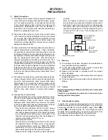
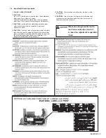
Good earth ground

Place this 
probe on 
each exposed
metal part.

AC VOLTMETER
(Having 1000 
ohms/volts,
or more sensitivity)

1500     10W

0.15   F  AC TYPE

Summary of Contents for CA-UXG45

Page 1: ... SYSTEM MB533 2006 6 UX G45B UX G45E UX G45EN UX G45EV Lead free solder used in the board material Sn Ag Cu melting point 219 Centigrade TABLE OF CONTENTS 1 PRECAUTIONS 1 3 2 SPECIFIC SERVICE INSTRUCTIONS 1 6 3 DISASSEMBLY 1 7 4 ADJUSTMENT 1 14 5 TROUBLESHOOTING 1 15 CA UXG45 SP UXG45 SP UXG45 ...

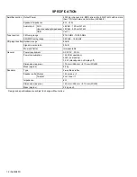
Page 2: ... 1 1 Tuner section FM tuning range 87 50 MHz 108 00 MHz AM MW tuning range 522 kHz 1 629 kHz CD player section Dynamic range 85 dB Signal to noise ratio 85 dB Wow and flutter Immeasurable General Power requirement AC 230 V 50 Hz Power consumption 145 W at operation 20 W on standby 0 9 W standby and on Display off Dimensions approx 175 mm 246 mm 415 mm W H D Mass approx 6 2 kg Speakers Type 2 way B...

Page 3: ...jack control shafts etc to be sure the product is safe to operate without danger of electrical shock Do not use a line isolation transformer during this check Plug the AC line cord directly into the AC outlet Using a Leakage Current Tester measure the leakage current from each exposed metal parts of the cabinet particular ly any exposed metal part having a return path to the chassis to a known goo...

Page 4: ...same safety characteristics as the recommended replacement parts shown in the Parts List of the Service Manual and may create shock fire or other hazards 4 The leads in the products are routed and dressed with ties clamps tubings barriers and the like to be separated from live parts high temperature parts moving parts and or sharp edges for the prevention of electric shock and fire hazard When ser...

Page 5: ...t uses visible and or invisible laser radiation and is equipped with safety switches which prevent emission of radiation when the drawer is open and the safety interlocks have failed or are defeated It is dangerous to defeat the safety switches 5 CAUTION If safety switches malfunction the laser is able to function 6 CAUTION Use of controls adjustments or performance of procedures other than those ...

Page 6: ...1 6 No MB533 SECTION 2 SPECIFIC SERVICE INSTRUCTIONS This service manual does not describe SPECIFIC SERVICE INSTRUCTIONS ...

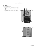
Page 7: ... 1 1 Removing the side panel See Fig 1 2 1 Remove the four screws A attaching the rear cover See Fig 1 2 Remove the six screws B attaching the side panel See Fig 1 3 Remove the four screws C attaching the side panel See Fig 2 Fig 1 Fig 2 A B B A A E C C ...

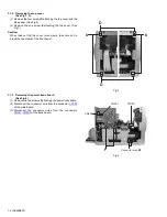
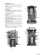
Page 8: ...ke out the top cover raise slowly take care not to break the two claws of the front panel Fig 3 3 1 3 Removing the power trans board See Fig 4 1 Remove the two screws F attaching the power trans board 2 Disconnect the connector wire from the connector CN103 of the main board 3 Disconnect the connector wires from the connectors CN901 CN902 of the trans board Fig 4 D D b b F CN901 CN902 CN103 Connec...

Page 9: ...ove the tow screws K attaching the main board and the front board See Fig 7 3 Disconnect the card wires from the connectors CN401 CN402 of the main board See Fig 7 4 Disconnect the card wire from the connector CN403 of the main board See Fig 7 5 Disconnect the parallel wire from the connector CN502 of the main board See Fig 7 6 Disconnect the connector wires from the connectors CN101 CN102 CN204 C...

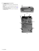
Page 10: ...res a on the bottom chassis See Fig 4 2 Remove the two screws N attaching the front panel See Fig 8 3 Disconnect the connector wire from the connector CN860 of the CD board See Fig 9 4 Disengage the four hooks b are remove the front panel as sembly See Fig 3 Fig 8 Fig 9 N CN860 R BN702 BN703 R R CN701 ...

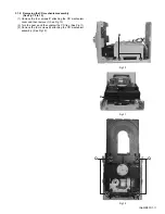
Page 11: ...Fig 10 to 12 1 Remove the four screws P attaching the CD mechanism cover and then remove it See Fig 10 2 Turn the gear c and then undraw the CD tray See Fig 11 3 Remove the four screws Q attaching the CD mechanism assembly See Fig 12 Fig 10 Fig 11 Fig 12 P c Q Q ...

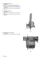
Page 12: ...s BN702 B703 of the CD board 3 Disconnect the card wire from the connector CN701 of the CD board 3 1 10 Removing the rear panel See Fig 5 13 1 Remove the one screw S attaching the rear panel See Fig 5 2 Disengage the two hooks d and remove the rear panel See Fig 13 Fig 13 3 1 11 Removing the power transformer See Fig 14 1 Remove the four screws T attaching the power transform er Fig 14 d T T ...

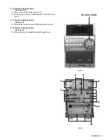
Page 13: ...15 2 Remove the four screws U attaching the VFD board See Fig 16 3 1 13 Removing the key board See Fig 16 1 Remove the fourteen screws V attaching the key board 3 1 14 Removing the jack board See Fig 16 1 Remove the four screws W attaching the jack board Fig 15 Fig 16 Volume knob U U V V V V V W ...

Page 14: ...1 14 No MB533 SECTION 4 ADJUSTMENT This service manual does not describe ADJUSTMENT ...

Page 15: ... No MB533 1 15 SECTION 5 TROUBLESHOOTING This service manual does not describe TROUBLESHOOTING ...

Page 16: ... No MB533 Audio Video Systems Category 10 1 1chome Ohwatari machi Maebashi city 371 8543 Japan Victor Company of Japan Limited VPT Printed in Japan ...

Page 17: ...blies are not available as service parts Contents Exploded view of general assembly and parts list Block No M1 Electrical parts list Block No 01 04 Packing materials and accessories parts list Block No M3 UX G45B UX G45E UX G45EN UX G45EV 3 2 3 5 3 12 MB533 ...

Page 18: ...eral assembly and parts list Block No M M M 1 Main boar VFD board Power Trans board Key board Jack board a 18 40 15 11 40 17 18 42 3 2 32 34 40 40 44 5 6 7 8 12 1 14 16 41 14 27 27 54 45 36 20 9 10 1 4 35 35 13 40 31 38 48 53 ...

Page 19: ...3 3 M Main board CD board The parts without symbol number are not service a 18 18 18 30 34 32 2 34 51 46 18 24 25 49 18 23 32 45 26 22 39 38 35 27 37 55 35 52 28 18 47 31 52 21 43 33 31 50 18 52 48 ...

Page 20: ...T 0 8mm 26 BI211011146001 POWER TRANS PT902 27 BIRT000608B1W SCREW 3xL8 x4 28 BI2031150102X1 SIDE PANEL R 30 BIBT000614B3X1 SCREW 3xL14 x2 31 BIBT000635S2X1 SCREW 3XL35 x2 32 BIBT000649 SCREW BT 3X12 x3 33 BI2031370101X1 BOTTM CHASSIS T 1 0mm 34 BI372130064BTS SCREW 3xL6 x4 35 BIRT000606S3 SCREW RT 3X8 M x6 36 BI2031390101X1 CD MECH HOLDER F T 1 0mm 37 BI2031400101X1 CD MECH HOLDER B T 1 0mm 38 BI...

Page 21: ...133 FR DIODE BI31SS133M000V7 D236 1SS133 FR DIODE BI31SS133M000V7 D361 1SS133 FR DIODE BI31SS133M000V7 D362 1SS133 FR DIODE BI31SS133M000V7 D363 1SS133 FR DIODE BI31SS133M000V7 D371 1SS133 FR DIODE BI31SS133M000V7 D401 1SS133 FR DIODE BI31SS133M000V7 D402 1SS133 FR DIODE BI31SS133M000V7 D403 1SS133 FR DIODE BI31SS133M000V7 D404 1SS133 FR DIODE BI31SS133M000V7 D405 1SS133 FR DIODE BI31SS133M000V7 D...

Page 22: ...BICM124101KP01 M CAPACITOR 0 12uF 100V C556 BICM124101KP01 M CAPACITOR 0 12uF 100V Symbol No Part No Part Name Description Local C557 BICE107160MP01 E CAPACITOR 100uF 16V C558 BICE107160MP01 E CAPACITOR 100uF 16V C559 BICE475500MP01 E CAPACITOR 4 7uF 50V C560 BICE475500MP01 E CAPACITOR 4 7uF 50V C561 BICE475500MP01 E CAPACITOR 4 7uF 50V C562 BICC471500JA04 C CAPACITOR 470pF C563 BICC471500JA04 C C...

Page 23: ... R403 BIRC1020105A00 C RESISTOR 1KΩ 1 10W Symbol No Part No Part Name Description Local R404 BIRC4730105A00 C RESISTOR 47KΩ 1 10W R406 BIRC3310085M00 C RESISTOR 330Ω 1 8W R407 BIRC1820085M00 C RESISTOR 1 8KΩ 1 8W R408 BIRC2220085N00 C RESISTOR 2 2KΩ 1 8W R411 BIRC4700105A00 C RESISTOR 47Ω 1 10W R420 BIRC1010105A00 C RESISTOR 100Ω 1 10W R421 BIRC1010105A00 C RESISTOR 100Ω 1 10W R422 BIRC1010105A00 ...

Page 24: ...KΩ 1 10W R676 BIRC4730105A00 C RESISTOR 47KΩ 1 10W R677 BIRC4730105A00 C RESISTOR 47KΩ 1 10W R678 BIRC4730105A00 C RESISTOR 47KΩ 1 10W R679 BIRC4730105A00 C RESISTOR 47KΩ 1 10W R680 BIRC4730105A00 C RESISTOR 47KΩ 1 10W R681 BIRC4730105A00 C RESISTOR 47KΩ 1 10W R682 BIRC4730105A00 C RESISTOR 47KΩ 1 10W Symbol No Part No Part Name Description Local R683 BIRC4730105A00 C RESISTOR 47KΩ 1 10W R684 BIRC...

Page 25: ...3160KA04 C CAPACITOR 0 068uF 16V C726 BICE106160MP01 E CAPACITOR 10uF 16V C727 BICC154100KA04 C CAPACITOR 0 15UF C728 BICC104500KA04 C CAPACITOR 0 1uF 50V C729 BICC102500KA04 C CAPACITOR 1000pF 50V C730 BICC222500KA04 C CAPACITOR 2200pF 50V C731 BICC333160KA04 C CAPACITOR 0 033UF C732 BICC104500KA04 C CAPACITOR 0 1uF 50V C733 BICC104500KA04 C CAPACITOR 0 1uF 50V C741 BICC391500JA04 C CAPACITOR 390...

Page 26: ... 8W J R858 BIRC2230105A00 C RESISTOR 22KΩ 1 10W R859 BIRC1030105A00 C RESISTOR 10KΩ 1 10W R860 BIRC2230105A00 C RESISTOR 22KΩ 1 10W R861 BIRC2200105A00 C RESISTOR 22Ω 1 10W R862 BIRC2200105A00 C RESISTOR 22Ω 1 10W R863 BIRC2200105A00 C RESISTOR 22Ω 1 10W R864 BIRC2200105A00 C RESISTOR 22Ω 1 10W R865 BIRC2200105A00 C RESISTOR 22Ω 1 10W R866 BIRC2200105A00 C RESISTOR 22Ω 1 10W Symbol No Part No Part...

Page 27: ...E CAPACITOR 3 3uF 50V R902 BIRC5620085M00 C RESISTOR 5 6KΩ 1 8W R903 BIRC3320085M00 C RESISTOR 3 3KΩ 1 8W R905 BIRC3300085M00 C RESISTOR 33Ω 1 8W R906 BIRC4720085M00 C RESISTOR 4 7KΩ 1 8W R907 BIRC1220085M00 C RESISTOR 1 2KΩ 1 8W R908 BIRC4720085M00 C RESISTOR 4 7KΩ 1 8W R909 BIRC1030085M00 C RESISTOR 10KΩ 1 8W J L901 BI2601102V LINE FILTER WIRE BN903 BI12P60178X WIRE 6P FOR MAIN CN103 CN901 BI12S...

Page 28: ...erials and accessories parts list Block No M M M 3 No additional supplemental order of WARRANTY CARDs are available P1 P5 P7 P2 P11 P4 P9 P10 P8 P6 P3 A8 A1 UX G45B A2 A3 A4 A5 A6 A7 P2 A1 UX G45E UX G45EN UX G45EV A2 ...

Page 29: ...291001 REGIST CARD G45B A 4 BATTERY x2 A 5 BIAN01351Y AM LOOP ANT A 6 BIAN01371Y ANT WIRE A 7 BI643UXG45020 REMOTE CONTROL UNIT A 8 BI644UXG45202S SPEAKER SYSTEM P 1 BI430002064001 CARTON P 2 BI470011031004 POLY BAG FOR INST BOOK P 3 BI470011057004 POLY BAG FOR ANT LOOP P 4 BI450012100000 POLY FOAM TOP FOR SPK P 5 BI450012101000 POLY FOAM BOTT FOR SPK P 6 BI450012097000 POLY FOAM FRONT FOR UNIT P ...

Page 30: ...ndard schematic diagrams Printed circuit boards 2 1 2 2 2 7 to 9 CD ROM No SML200606 MICRO COMPONENT SYSTEM No MB533SCH 2006 6 COPYRIGHT 2006 Victor Company of Japan Limited Lead free solder used in the board material Sn Ag Cu melting point 219 Centigrade CA UXG45 SP UXG45 SP UXG45 ...

Page 31: ...ponent parts appearing on the silk screen printed side parts side of the PWB diagrams the parts that are printed over with black such as the resistor diode and ICP or identified by the mark nearby are critical for safety ...

Page 32: ...CK JK991 Out Vcc Out Vcc Out Vcc IC113 RS202 C115 C116 15V VP VP C106 C107 RS603M VFD AC 28V 9V 9V ZD501 ZD502 4 7V 4 7V TREBLE BASS CIRCUIT 3 3V 9V TAPE CD TU AUX BASS TRE 18dB AMP VOL REC AMP STANDBY LED D625 Q625 5V CONTROL DIMMER LED D626 CN401 CN402 CN801 CN802 Q354 Q352 9V VCC9V CONTROL VCC3 3V CONTROL FILTER AC SUB TRANS PT902 IN4001 AC RELAY RY901 AC RELAY CONTROL IC901 DRAM IC802 OSC C805...

Page 33: ...C VFD AC VFD AC AC 12V AC 12V GND GND GND TO MAIN PCB CON ASSY2 5 5P BN102 Q908 C908 R903 C906 R902 R908 D908 IN4001 R904 R909 C905 Q909 DTC114YS DTC114YS 2R 2R 3 3U 50 3 3K A N M 47U 50 220U 10 10K A 5 6K A 4 7K A BOARD TO BOARD TO AMP CON ASSY2 0 6P PWR INH GND DC 12V AC RELAY DETECT MICOM 5V 1 2 3 4 5 6 BN903 IC901 Out In Gnd NJM78L05 D907 D904 D903 PT902 FC901 FC902 L901 F901 R906 Q903 R907 R9...

Page 34: ...z B E E N E V A U S U J U U W U Y UX 24 HR 24 HR 24 HR 24 HR 24 HR STEP CLOCK VERSION VERSION E U A AM kHz STEP R 4 3 8 R 4 6 4 R 4 6 5 R 4 6 6 R 4 6 8 R 4 6 9 J C B E EN EV A US UJ U UW UY UX D 4 2 1 D 4 2 2 D 4 2 3 VERSION OPTION DIODE OPTION HP 3 5 PJ 321B C991 1000P C992 1000P 1SS133 1SS133 FRONT PCB 3 JK971 CON ASSY2 0 4P C665 P 01 20 G 01 20 0 1U P03 P02 P01 IC651 G01 G01 R655 C661 0 1U C662...

Page 35: ...18 0 1U C517 220U 10 C516 0 1U C514 C512 8 2 0 0 P 0 01U 1 2K C 5 0 6 C 5 0 2 R 5 0 4 R516 4 7K R517 4 7K R 5 0 2 2 7 0 2 7 0 R510 5 6 0 A R509 R501 2 7 0 0 P C328 4 7 A R330 2 2K R 3 2 7 2SC3052 Q 3 2 4 2 2 0 U 1 0 C326 M 5600P C 3 2 5 560P C 3 2 4 C 3 2 3 0 1U C 3 2 2 47U 16 R 3 2 6 1K C 3 2 1 47U 16 C 3 2 0 R 3 2 3 TA 6 2 TA 2 7 TA 5 9 TA 5 8 TA 6 0 1 0 0 47U 16 D 3 2 1 1SS133 D 3 2 0 1SS133 R ...

Page 36: ...R R153 33 A R150 120 A 3P 2 5 3 2 1 CN141 FAN D142 1SS133 2SC3052 Q161 KTA1273 ZD162 UZ6 2BSB R163 2 2K C165 10 50 MC2838 R260 1K R262 15K D232 1SS133 R259 1K A R211 100 1W R212 R215 56K C217 5p R216 56K C218 5p 100 1W R261 15K R263 1K R269 150K 100K R174 4 7U 50 C173 22U 16 C174 3 3K R175 100U 16 C175 5 6B ZD175 R176 390 R177 N M R173 47 C172 1U 50 Q173 JW 680K D171 R171 C171 R172 18K 2 2 0 0 P D...

Page 37: ... R717 C719 C718 R714 1000P 0 1U C717 0 1U C716 R713 4 7U 50 NM NM R712 820p C714 6 8 0 0 P C713 C715 0 1U 10K 0 033U C720 1M R716 22K 0 4 7 U R715 18K C712 R711 6 2K R709 C711 C705 1000P C706 1000P C707 C708 0 047U 1 2 3 4 5 6 7 8 9 1 0 11 1 2 RFM RFO EQI EQO EFMI VCC FRSH FSET FLB FGD FSI TGU 3 6 3 5 3 4 3 3 3 2 3 1 3 0 2 9 2 8 2 7 2 6 2 5 ATSC LPFT TEIO TZC SSTOP GND FEO FEM TEO TEM SLP SLO SLM ...

Page 38: ...9 J218 J144 J143 J143 J142 J141 J140 J139 L131 J136 J147 J135 J134 J138 R116 R112 R161 J148 J149 C114 R520 C528 C526 C527 J234 C376 C525 C213 C557 C214 J210 J207 J205 BN302 D301 J216 C503 C504 R504 J211 J212 R510 J213 C310 J206 C326 Q327 Q326 Q325 R330 R331 C332 J452 C325 C321 C320 L320 L321 Q322 R325 D321 D320 Q320 L381 J203 J204 C322 J420 J450 J449 J447 R464 R519 R518 R344 R328 R466 R465 J454 J4...

Page 39: ...3 MD1 4 MD2 5 MD3 6 MD4 7 MD5 8 MD6 9 MD7 10 MADDR 11 MCS 12 MCK 13 MDA 14 DEC 17 MLT 15 DSP 16 ISTAT 18 IN SW 19 H RDY 20 H OUT 1 CLOSE SW 2 GND 3 OPEN SW 4 MOTOR 5 MOTOR X860 R876 JW769 JW730 JW770 JW742 C858 C859 JW768 JW767 L860 Q896 Q862 CN860 JW777 JW802 JW778 JW779 JW780 JW781 JW782 JW707 JW783 JW790 BN703 1 HOST CLK 2 H IN M OUT 3 USB ON OFF 4 CD ON CN802 5 SAFETY 6 H SENSE 7 CD CL MO 8 CD...

Page 40: ... LIVE NEUTRAL CN901 CN902 TRANS AC IN Q903 R906 D901 D902 D903 D905 D904 C904 C903 IC901 C908 C905 R907 R908 D908 D907 R909 BN903 Q908 Q909 C906 R903 R902 CAUTION ATTENTION REPLACS WITH SAME TYPE AND RATING FUSE S REMPLACER PAR UN LES FUSIBLE S DE MEME TYPE ET DE MEME VALEUR PbF MODEL UX G45 P T PCB PART NO 25 1513 G01V VER MP PWR DETECT INHIBIT MICON GND PWR RELLAY DC 12V M 5 V ...

Page 41: ...Victor Company of Japan Limited No MB533SCH Printed in Japan VPT Audio Video Systems Category 10 1 1chome Ohwatari machi Maebashi city 371 8543 Japan ...

Reviews: