

MX-KA7
1-14
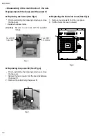
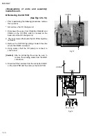
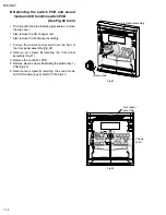
Removing the switch PCB and sound
mode and CD function switch PCB
(See Fig.20 to 23)
Prior to performing the following procedures, remove
the top cover.
Also remove the CD changer unit.
Also remove the front panel assembly.
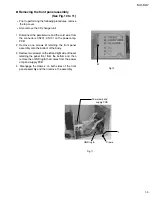
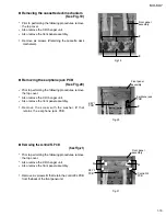
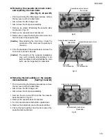
1. Pull out the volume control knob from the front of
the front panel assembly.(Fig.22)
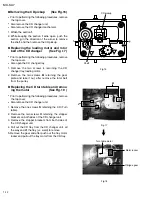
2. Remove six screws
Q
retaining the front panel
assembly.(Fig.21)
3. Remove the control/FL PCB.
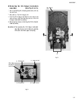
4. Remove eleven screws
R
retaining the switch (key 1)
PCB.(Fig.20)
5. Remove two screws
S
retaining the sound mode
and CD function (key 2) switch PCB.(Fig.21)
Fig.22
Fig.23
Volume knob
Front panel
assembly
Volume
shaft
Front panel assembly
Summary of Contents for CA-MXKA7
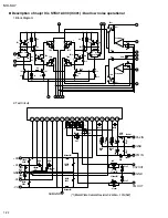
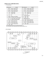
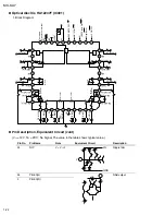
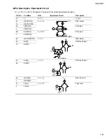
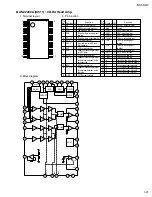
Page 23: ...MX KA7 1 23 1 Pin descriptions 2 Block diagram Optical disc ICs BA5936S IC621 ...
Page 35: ...A B C D E F G 1 2 3 4 5 2 1 MX KA7 n Tuner section ...
Page 36: ...A B C D E F G 1 2 3 4 5 2 2 n Main section MX KA7 ...
Page 37: ...A B C D E F G 1 2 3 4 5 2 3 MX KA7 n CD section ...
Page 38: ...A B C D E F G 1 2 3 4 5 2 4 MX KA7 n Amplifier ...
Page 39: ...A B C D E F G 1 2 3 4 5 2 5 MX KA7 n FL Display and CPU Control ...
Page 40: ...A B C D E F G 1 2 3 4 5 2 6 MX KA7 n Power transformer section ...
Page 41: ...A B C D E F G 1 2 3 4 5 2 7 MX KA7 n Block diagram ...
Page 42: ...A B C D E F G 1 2 3 4 5 2 8 MX KA7 n Wiring diagram ...
Page 43: ...A B C D E F G 1 2 3 4 5 2 9 MX KA7 n Main top PWB ...
Page 44: ...A B C D E F G 1 2 3 4 5 2 10 MX KA7 n Main bottom PWB ...
Page 45: ...A B C D E F G 1 2 3 4 5 2 11 MX KA7 n FL Display and CPU TOP ...
Page 46: ...A B C D E F G 1 2 3 4 5 2 12 MX KA7 n FL Display and CPU BOTTOM ...
Page 47: ...A B C D E F G 1 2 3 4 5 2 13 MX KA7 n Power Amp PWB ...
Page 48: ...A B C D E F G 1 2 3 4 5 2 14 MX KA7 n Power trans PWB ...
Page 59: ...3 11 MEMO ...