


No. 51754
AV-29RF6
14
BASIC OPERATION OF SERVICE MENU
1. The adjustment using SERVICE MENU
The following adjustment items use the SERVICE MENU in the series of the adjustment. The adjustments are made on the basis of the
initial setting values. The adjustment values which adjust the screen to the optimum condition can be different from the initial setting values.
With the SERVICE NEMU, various settings can be made, and they are broadly classified in the following items of settings.
IF
・・・・・・・・・・・・・・・・・・・・・・・・・
Adjustment of the IF circuits.
V/C
・・・・・・・・・・・・・・・・・・・・・・・
Adjustment of the VIDEO/CHROMA circuit.
AUDIO
・・・・・・・・・・・・・・・・・・・・
Adjustment of the sound circuit
[Do not adjust]
.
DEF
・・・・・・・・・・・・・・・・・・・・・・・
Adjustment of the DEFLECTION circuit for each aspect mode given below
REGULAR (50/60Hz)
ZOOM (50/60Hz)
16:9 (50/60Hz)
VSM PRESET
・・・・・・・・・・・・・・
Adjustment of the initial setting values of VSM condition as BRIGHT, STANDARD and SOFT.
(VSM : Video Status Memory)
WB PRESET
・・・・・・・・・・・・・・・
Adjustment of the initial setting value of WHITE BALANCE PRESET values as COOL, MID and WARM.
AUTO PROGRAM
・・・・・・・・・・・
By turning the power switch on, you can get the state of AUTO PROGRAM
[Do not adjust]
.
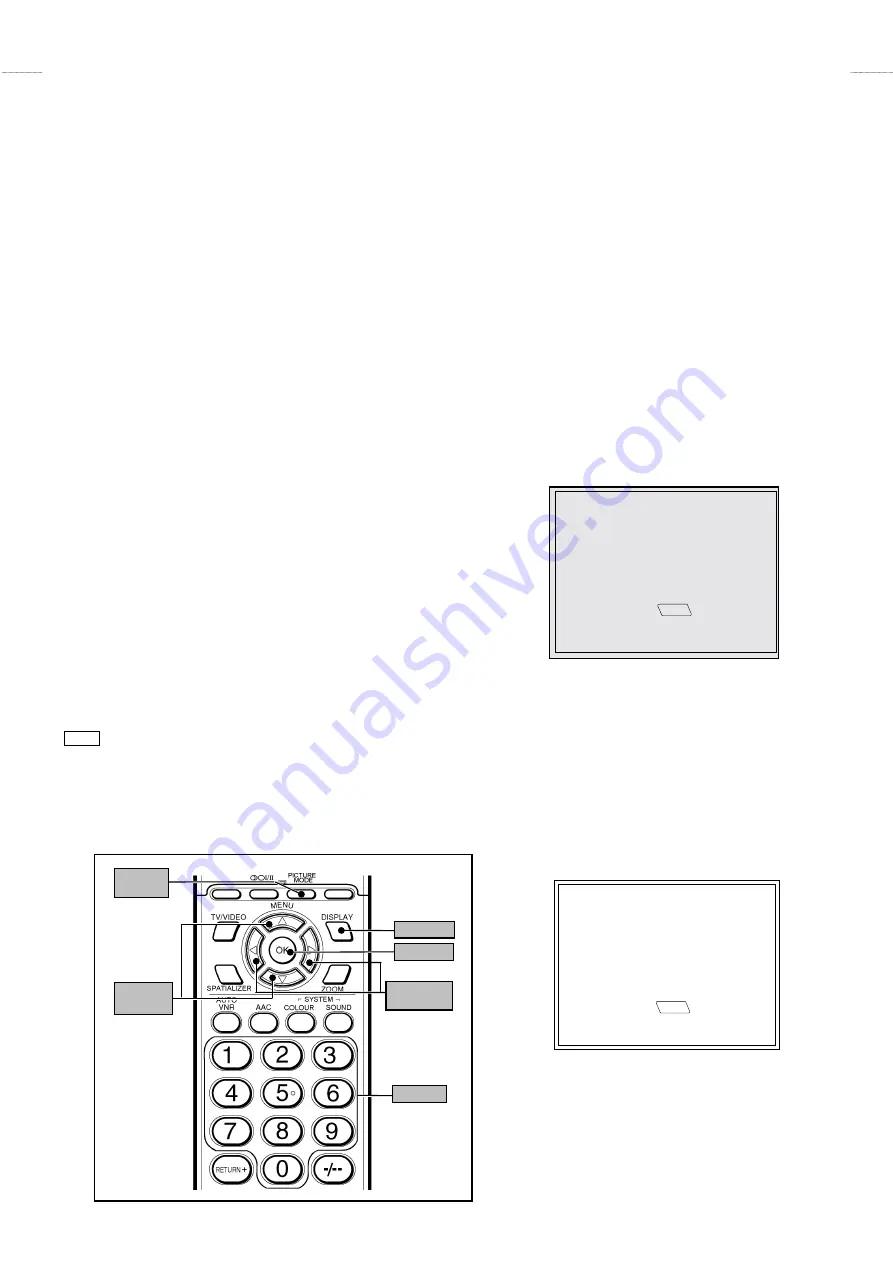
2. Key operation of the SERVICE MENU
[Enter to SERVICE MENU]
Press the
DISPLAY
key and the
PICTURE MODE
key of the REMOTE CONTROL
UNIT simultaneously. Then enter the SERVICE MENU mode as shown in Fig.1.
[Exit from SERVICE MENU]
When complete the adjustment work, press the
DISPLAY
key to return to the main
SERVICE MENU. And then press the
DISPLAY
key again, return to the normal
screen.
[Select the SUB MENU from MAIN MENU]
In main SERVICE MENU, press the 1
~
7 key of the remote control unit, to select any
of the adjustment items.
The colours which selected item characters are changed.
[Method of setting]
1. IF
[VCO]
①
1 Key
・・・・・・・・・・
Select
1.IF
.
②
The VCO (CW) screen will be displayed.
③
DISPLAY Key
・・・
As you press this key, you will return to the
SERVICE MENU
.
SERVICE MENU
1. IF
2. V/C
3. AUDIO
4. DEF
5. VSM PRESET
6. WB PRESET
7. AUTO PROGRAM (OFF)
1-7 : SELECT
DISP : EXIT
SERVICE MENU
JVC JK ASIA V
**
**
**
**
M
*******
*******
*******
*******
-
*****
*****
*****
*****
Fig.1
SUB MENU 1.IF(VCO)
VCO (CW)
**
**
**
**
.
**
**
**
**
MHz : CH
**
**
**
**
TOO HIGH
ABOVE REFERENCE
JUST REFERENCE
BELOW REFERENCE
TOO LOW
DISP
: EXIT
KEY ASSIGNMENT OF REMOTE CONTROL UNIT
PICTURE
MODE
MENU
UP/DOWN
MENU
LEFT/RIGHT
DISPLAY
Ten key
OK
Summary of Contents for AV28R100EKS
Page 67: ...AV 29RF6 AV 29RF6 No 51754 No 51754 3 2 5 2 6 CIRCUIT DIAGRAMS MAIN PWB CIRCUIT DIAGRAM ...
Page 68: ...AV 29RF6 AV 29RF6 No 51754 No 51754 4 2 7 2 8 ...
Page 69: ...AV 29RF6 AV 29RF6 No 51754 No 51754 5 54 1 2 9 2 10 POWER DEF PWB CIRCUIT DIAGRAM ...
Page 70: ...AV 29RF6 AV 29RF6 No 51754 No 51754 6 105 5 2 11 2 12 CRT SOCKET PWB CIRCUIT DIAGRAM ...
Page 71: ...AV 29RF6 AV 29RF6 No 51754 No 51754 7 103 7 2 13 2 14 FRONT CONTROL PWB CIRCUIT DIAGRAM ...
Page 72: ...AV 29RF6 AV 29RF6 No 51754 No 51754 8 2 15 2 16 AV SEL PWB CIRCUIT DIAGRAM ...
Page 73: ...AV 29RF6 AV 29RF6 No 51754 No 51754 9 FRONT 2 17 2 18 PATTERN DIAGRAMS MAIN PWB PATTERN ...
Page 74: ...AV 29RF6 AV 29RF6 No 51754 No 51754 10 FRONT TP E TP 91 B1 2 19 2 20 POWER DEF PWB PATTERN ...
Page 75: ...AV 29RF6 AV 29RF6 No 51754 No 51754 11 TOP 2 21 2 22 CRT SOCKET PWB PATTERN ...
Page 76: ...AV 29RF6 AV 29RF6 No 51754 No 51754 12 FRONT FRONT 2 23 2 24 FRONT CONTROL PWB PATTERN ...
Page 77: ...AV 29RF6 AV 29RF6 No 51754 No 51754 13 TOP 29RF6 HSAE VP0007 DP6053 2 25 AV SEL PWB PATTERN ...


