background image

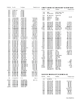
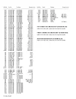
(No.YA447)3-13

R107

NRSA63J-472X

MG RESISTOR

4.7k

 1/16W J

R108

NRSA63J-222X

MG RESISTOR

2.2k

 1/16W J

R109

NRSA63J-222X

MG RESISTOR

2.2k

 1/16W J

R110

NRSA63J-222X

MG RESISTOR

2.2k

 1/16W J

R341

NRSA63J-0R0X

MG RESISTOR

0

 1/16W J

R344

NRSA63J-220X

MG RESISTOR

22

 1/16W J

R345

NRSA63J-102X

MG RESISTOR

1k

 1/16W J

R411

NRSA63J-222X

MG RESISTOR

2.2k

 1/16W J

R412

NRSA63J-222X

MG RESISTOR

2.2k

 1/16W J

R421

NRSA63J-103X

MG RESISTOR

10k

 1/16W J

R426

NRSA63J-123X

MG RESISTOR

12k

 1/16W J

R427

NRSA63J-682X

MG RESISTOR

6.8k

 1/16W J

R430

NRSA63J-123X

MG RESISTOR

12k

 1/16W J

R432

QRX01GJ-2R2

MF RESISTOR

2.2

 1W J

R433

QRE121J-3R9Y

C RESISTOR

3.9

 1/2W J

R434

NRSA63J-682X

MG RESISTOR

6.8k

 1/16W J

R438

NRSA63J-105X

MG RESISTOR

1M

 1/16W J

R440

QRG01GJ-331

OMF RESISTOR

330

 1W J

R448

QRE121J-1R0Y

C RESISTOR

1

 1/2W J

R461

QRE121J-823Y

C RESISTOR

82k

 1/2W J

R462

QRL039J-330

OMF RESISTOR

33

 3W J

R471

NRSA63J-274X

MG RESISTOR

270k

 1/16W J

R472

NRSA63J-103X

MG RESISTOR

10k

 1/16W J

R473

NRSA63J-683X

MG RESISTOR

68k

 1/16W J

R474

NRSA63J-224X

MG RESISTOR

220k

 1/16W J

R481

NRSA63J-124X

MG RESISTOR

120k

 1/16W J

R482

NRSA63J-683X

MG RESISTOR

68k

 1/16W J

R483

NRSA63J-682X

MG RESISTOR

6.8k

 1/16W J

R484

NRSA63J-562X

MG RESISTOR

5.6k

 1/16W J

R485

NRSA63J-333X

MG RESISTOR

33k

 1/16W J

R486

NRSA63J-332X

MG RESISTOR

3.3k

 1/16W J

R487

NRSA63J-154X

MG RESISTOR

150k

 1/16W J

R488

NRSA63J-104X

MG RESISTOR

100k

 1/16W J

R490

NRSA63J-103X

MG RESISTOR

10k

 1/16W J

R491

NRSA63J-683X

MG RESISTOR

68k

 1/16W J

R492

NRSA63J-152X

MG RESISTOR

1.5k

 1/16W J

R493

NRSA63J-223X

MG RESISTOR

22k

 1/16W J

R494

NRSA63J-562X

MG RESISTOR

5.6k

 1/16W J

R496

NRSA63J-472X

MG RESISTOR

4.7k

 1/16W J

R497

NRSA63J-222X

MG RESISTOR

2.2k

 1/16W J

R498

NRSA63J-223X

MG RESISTOR

22k

 1/16W J

R499

NRSA63J-473X

MG RESISTOR

47k

 1/16W J

R520

NRSA63J-471X

MG RESISTOR

470

 1/16W J

R521

NRSA63J-104X

MG RESISTOR

100k

 1/16W J

R522

QRE121J-220Y

C RESISTOR

22

 1/2W J

R523

QRL029J-271

OMF RESISTOR

270

 2W J

R524

QRL039J-221

OMF RESISTOR

220

 3W J

R525

QRL039J-221

OMF RESISTOR

220

 3W J

R527

QRL039J-393

OMF RESISTOR

39k

 3W J

R528

QRE121J-471Y

C RESISTOR

470

 1/2W J

R530

QRZ9017-4R7

FUSI RESISTOR

4.7

 1/4W J

R533

QRZ9017-4R7

FUSI RESISTOR

4.7

 1/4W J

R551

QRZ9021-1R0

FUSI RESISTOR

1

 1W J

R552

QRZ9021-1R0

FUSI RESISTOR

1

 1W J

R554

NRSA63J-182X

MG RESISTOR

1.8k

 1/16W J

R571

QRZ0225-2R2

UNF RESISTOR

2.2

 7W K

R572

QRA14CF-1202Y

CMF RESISTOR

12k

 1/4W F

R573

NRSA63J-332X

MG RESISTOR

3.3k

 1/16W J

R574

QRE121J-183Y

C RESISTOR

18k

 1/2W J

R575

NRSA63J-222X

MG RESISTOR

2.2k

 1/16W J

R581

QRE121J-822Y

C RESISTOR

8.2k

 1/2W J

R582

QRE121J-823Y

C RESISTOR

82k

 1/2W J

R583

QRE121J-184Y

C RESISTOR

180k

 1/2W J

R601

NRSA63J-0R0X

MG RESISTOR

0

 1/16W J

R602

NRSA63J-0R0X

MG RESISTOR

0

 1/16W J

R603

NRSA63J-102X

MG RESISTOR

1k

 1/16W J

R606

QRE121J-2R2Y

C RESISTOR

2.2

 1/2W J

R607

QRE121J-2R2Y

C RESISTOR

2.2

 1/2W J

R609

NRSA63J-273X

MG RESISTOR

27k

 1/16W J

R610

NRSA63J-104X

MG RESISTOR

100k

 1/16W J

R611

NRSA63J-103X

MG RESISTOR

10k

 1/16W J

R612

NRSA63J-104X

MG RESISTOR

100k

 1/16W J

R614

NRSA63J-104X

MG RESISTOR

100k

 1/16W J

R620

NRSA63J-103X

MG RESISTOR

10k

 1/16W J

R621

NRSA63J-222X

MG RESISTOR

2.2k

 1/16W J

R622

NRSA63J-103X

MG RESISTOR

10k

 1/16W J

R623

NRSA63J-333X

MG RESISTOR

33k

 1/16W J

R624

NRSA63J-683X

MG RESISTOR

68k

 1/16W J

R629

NRSA63J-222X

MG RESISTOR

2.2k

 1/16W J

R630

NRSA63J-222X

MG RESISTOR

2.2k

 1/16W J

R632

NRSA63J-102X

MG RESISTOR

1k

 1/16W J

R701

NRSA63J-123X

MG RESISTOR

12k

 1/16W J

R702

NRSA63J-471X

MG RESISTOR

470

 1/16W J

R703

NRSA63J-101X

MG RESISTOR

100

 1/16W J

R704

NRSA63J-101X

MG RESISTOR

100

 1/16W J

R705

NRSA63J-393X

MG RESISTOR

39k

 1/16W J

R706

NRSA63J-221X

MG RESISTOR

220

 1/16W J

Ref No.

Part No.

Part Name

Description Local

R707

NRSA63J-563X

MG RESISTOR

56k

 1/16W J

R708

NRSA63J-104X

MG RESISTOR

100k

 1/16W J

R709

NRSA63J-105X

MG RESISTOR

1M

 1/16W J

R711

QRE141J-562Y

C RESISTOR

5.6k

 1/4W J

R712

NRSA63J-103X

MG RESISTOR

10k

 1/16W J

R713

QRE141J-562Y

C RESISTOR

5.6k

 1/4W J

R714

NRSA63J-103X

MG RESISTOR

10k

 1/16W J

R715

NRSA63J-391X

MG RESISTOR

390

 1/16W J

R716

NRSA63J-562X

MG RESISTOR

5.6k

 1/16W J

R717

NRSA63J-103X

MG RESISTOR

10k

 1/16W J

R718

NRSA63J-562X

MG RESISTOR

5.6k

 1/16W J

R719

NRSA63J-103X

MG RESISTOR

10k

 1/16W J

R720

QRE141J-0R0Y

C RESISTOR

0

 1/4W J

R721

NRSA63J-0R0X

MG RESISTOR

0

 1/16W J

R722

NRSA63J-471X

MG RESISTOR

470

 1/16W J

R723

NRSA63J-471X

MG RESISTOR

470

 1/16W J

R724

NRSA63J-102X

MG RESISTOR

1k

 1/16W J

R725

NRSA63J-470X

MG RESISTOR

47

 1/16W J

R726

NRSA63J-273X

MG RESISTOR

27k

 1/16W J

R727

NRSA63J-103X

MG RESISTOR

10k

 1/16W J

R728

QRE141J-101Y

C RESISTOR

100

 1/4W J

R730

QRE141J-151Y

C RESISTOR

150

 1/4W J

R731

NRSA63J-102X

MG RESISTOR

1k

 1/16W J

R732

NRSA63J-102X

MG RESISTOR

1k

 1/16W J

R733

NRSA63J-101X

MG RESISTOR

100

 1/16W J

R734

NRSA63J-101X

MG RESISTOR

100

 1/16W J

R735

NRSA63J-101X

MG RESISTOR

100

 1/16W J

R736

QRE141J-101Y

C RESISTOR

100

 1/4W J

R737

NRSA63J-101X

MG RESISTOR

100

 1/16W J

R738

NRSA63J-101X

MG RESISTOR

100

 1/16W J

R739

NRSA63J-101X

MG RESISTOR

100

 1/16W J

R740

NRSA63J-153X

MG RESISTOR

15k

 1/16W J

R741

NRSA63J-221X

MG RESISTOR

220

 1/16W J

R742

NRSA63J-221X

MG RESISTOR

220

 1/16W J

R743

NRSA63J-332X

MG RESISTOR

3.3k

 1/16W J

R744

NRSA63J-221X

MG RESISTOR

220

 1/16W J

R745

NRSA63J-332X

MG RESISTOR

3.3k

 1/16W J

R746

NRSA63J-103X

MG RESISTOR

10k

 1/16W J

R747

NRSA63J-101X

MG RESISTOR

100

 1/16W J

R748

NRSA63J-272X

MG RESISTOR

2.7k

 1/16W J

R749

QRE141J-102Y

C RESISTOR

1k

 1/4W J

R750

NRSA63J-103X

MG RESISTOR

10k

 1/16W J

R751

NRSA63J-102X

MG RESISTOR

1k

 1/16W J

R752

QRE141J-101Y

C RESISTOR

100

 1/4W J

R753

NRSA63J-122X

MG RESISTOR

1.2k

 1/16W J

R754

NRSA63J-221X

MG RESISTOR

220

 1/16W J

R755

NRSA63J-122X

MG RESISTOR

1.2k

 1/16W J

R756

NRSA63J-103X

MG RESISTOR

10k

 1/16W J

R757

NRSA63J-472X

MG RESISTOR

4.7k

 1/16W J

R758

NRSA63J-332X

MG RESISTOR

3.3k

 1/16W J

R759

NRSA63J-332X

MG RESISTOR

3.3k

 1/16W J

R760

NRSA63J-101X

MG RESISTOR

100

 1/16W J

R761

NRSA63J-101X

MG RESISTOR

100

 1/16W J

R762

NRSA63J-221X

MG RESISTOR

220

 1/16W J

R763

NRSA63J-221X

MG RESISTOR

220

 1/16W J

R764

NRSA63J-221X

MG RESISTOR

220

 1/16W J

R765

NRSA63J-221X

MG RESISTOR

220

 1/16W J

R768

NRSA63J-101X

MG RESISTOR

100

 1/16W J

R769

NRSA63J-103X

MG RESISTOR

10k

 1/16W J

R770

NRSA63J-0R0X

MG RESISTOR

0

 1/16W J

R771

QRE141J-102Y

C RESISTOR

1k

 1/4W J

R772

QRE141J-562Y

C RESISTOR

5.6k

 1/4W J

R773

NRSA63J-103X

MG RESISTOR

10k

 1/16W J

R774

NRSA63J-562X

MG RESISTOR

5.6k

 1/16W J

R775

NRSA63J-103X

MG RESISTOR

10k

 1/16W J

R776

NRSA63J-153X

MG RESISTOR

15k

 1/16W J

R777

NRSA63J-101X

MG RESISTOR

100

 1/16W J

R779

NRSA63J-101X

MG RESISTOR

100

 1/16W J

R780

NRSA63J-101X

MG RESISTOR

100

 1/16W J

R781

NRSA63J-101X

MG RESISTOR

100

 1/16W J

R782

NRSA63J-122X

MG RESISTOR

1.2k

 1/16W J

R783

NRSA63J-103X

MG RESISTOR

10k

 1/16W J

R784

NRSA63J-103X

MG RESISTOR

10k

 1/16W J

R785

NRSA63J-103X

MG RESISTOR

10k

 1/16W J

R786

NRSA63J-750X

MG RESISTOR

75

 1/16W J

R787

NRSA63J-472X

MG RESISTOR

4.7k

 1/16W J

R788

NRSA63J-0R0X

MG RESISTOR

0

 1/16W J

R790

NRSA63J-102X

MG RESISTOR

1k

 1/16W J

R792

QRE141J-330Y

C RESISTOR

33

 1/4W J

R793

NRSA63J-101X

MG RESISTOR

100

 1/16W J

R794

NRSA63J-222X

MG RESISTOR

2.2k

 1/16W J

R795

NRSA63J-104X

MG RESISTOR

100k

 1/16W J

R796

NRSA63J-102X

MG RESISTOR

1k

 1/16W J

R797

NRSA63J-683X

MG RESISTOR

68k

 1/16W J

R798

NRSA63J-473X

MG RESISTOR

47k

 1/16W J

R801

NRSA63J-750X

MG RESISTOR

75

 1/16W J

R802

NRSA63J-0R0X

MG RESISTOR

0

 1/16W J

Ref No.

Part No.

Part Name

Description Local

Summary of Contents for AV-2986ME

Page 1: ...f Japan Limited No YA447 2006 9 FLAT COLOUR TELEVISION YA447 2006 9 AV 2986ME AV 29MS26 AV 29MX76 G TABLE OF CONTENTS 1 PRECAUTION 1 3 2 SPECIFIC SERVICE INSTRUCTIONS 1 4 3 DISASSEMBLY 1 6 4 ADJUSTMENT 1 12 5 TROUBLESHOOTING 1 32 BASIC CHASSIS CW3 ...

Page 2: ...5 MHz 4 25 MHz NTSC 3 58 MHz 4 43 MHz Power Input AC220 V AC240 V 50 Hz 60 Hz AC110 V AC240 V 50 Hz 60 Hz Power Consumption 170W Max 109W Avg Picture Tube 29 inch aspect ratio 4 3 flat square type tinted High Voltage 31 5 kV 1 kV 1 5kV Speaker 6 5 cm 13 cm oval type 2 Audio Power Output 10 W 10 W Rated power output Aerial Input 75 Ω unbalanced coaxial Video Audio Input 1 2 3 Component Video VIDEO ...

Page 3: ...or alternatives approved by the manufacturer of the complete product 7 Do not check high voltage by drawing an arc Use a high voltage meter or a high voltage probe with a VTVM Discharge the picture tube before attempting meter connection by connecting a clip lead to the ground frame and connecting the other end of the lead through a 10kΩ 2W resistor to the anode button 8 When service is required o...

Page 4: ...STANDARD and SOFT in the PICTURE MODE RETURN This function can set a channel frequently view to the Return Channel and you can view that channel at any time with one touch AI ECO SENSOR This function can adjust TV screen contrast according to the brightness of your room MaxxBass MaxxBass enhances bass sound that cannot be reproduced by normal speakers to be heard by our ears 2 2 MAIN DIFFERENCE LI...

Page 5: ...fOut O Automatic Volume Levelling sound IF input subcar rier reference output external reference signal input for I signalmixer for DVB operation 97 REMOTE I Remote control 34 L3 I Audio L3 input left signal 98 PW_LED I POWER LED control 35 R3 I Audio R3 input right signal 99 PW_LED I POWER LED control 36 L OUT O Audio L output 100 V1 8C2 I 1 8V 37 R OUT O Audio R output 101 VssC2 GND 38 DecsDem D...

Page 6: ...F as shown in Fig 2 the control base can be removed If necessary take off the wire connectors etc 3 1 5 REMOVING THE CHOKE COIL Remove the REAR COVER 1 Remove the 2 screws G as shown in Fig 1 2 Withdraw the CHOKE COIL 3 1 6 REMOVING THE SPEAKER Remove the REAR COVER 1 Remove the 2 screws H as shown in Fig 1 2 Withdraw the SPEAKER backward 3 Follow the same steps when removing the other hand SPEAKE...

Page 7: ... H CHASSIS BASE CONTROL BASE FRONT SIDE Fig 2 F E D CLAW under side POWER CORD CHASSIS BASE AV TERMINAL BOARD REAR COVER SPEAKER SPEAKER CRT SOCKET PWB FRONT CONTROL PWB CONTROL BASE FRONT CABINET MAIN PWB B CLAW under side B Fig 2 G CHOKE PWB ...

Page 8: ...M CONSTANT SET If the value is different select the setting item with the MENU key and set the correct value with the MENU key 5 Press the OK key to memorize the setting value 6 Press the DISPLAY key twice and return to the normal screen 5 Receiving channel setting Refer to the OPERATING INSTRUCTIONS and set the receive channels Channels Preset as described 6 User settings Check the user setting i...

Page 9: ...BLUE BACK MUTE NO COLOUR AUTO NO YES ECO SENSOR ECO INTER CARRIER NO SURROUND YES PICTURE BOOSTER NO COMPONENT YES PIP YES NO YES S INPUT YES MAXX BASS YES Setting item Setting position POWER Off CHANNEL PR 1 VOLUME 15 Setting item Setting position CHANNEL PR1 VOLUME 15 PICTURE MODE BRIGHT DISPLAY Indicated TV VIDEO TV CINEMA SURROUND OFF Setting item Setting position PICTURE MODE BRIGHT CONTRAST ...

Page 10: ...LUE BACK ON BEEP ON Setting item Setting value 1 IF 1 VCO 2 DELAY POINT 2 V C 1 SCREEN READ DATA 2 CUTOFF CUT OFF THEATER B G 3 WDR R G B 4 BRIGHT TV VDO 1 2 3 5 CONT TV VDO 1 2 3 6 COLOUR TV VDO 1 2 3 7 TINT TV VDO 1 2 3 THEATER 8 SHARP TV VDO 1 2 3 9 Y DELAY TV VDO 1 2 3 S VDO 10 TINT DVD TV VDO THEATER 11 AMP T SHARP TV VDO 12 TWIN CONT TV VDO 3 AUDIO Do not adjust 1 DCXO ADJ 2 NICAM lower ERRL...

Page 11: ...the tweezers and remove the chip part Transistors diodes variable resistors etc 1 Apply extra solder to each lead 2 As shown in the figure push the part with tweezers and alternately melt the solder at each lead Shift and remove the chip part NOTE After removing the part remove remaining solder from the pattern 2 How to install Chip parts Resistors capacitors etc 1 Apply solder to the pattern as i...

Page 12: ...G BEFORE ADJUSTMENT Unless otherwise specified in the adjustment items preset the following functions with the REMOTE CONTROL UNIT 4 3 MEASURING INSTRUMENT AND FIXTURES 1 DC voltmeter or digital voltmeter 2 Oscilloscope 3 HV voltmeter 4 Signal generator Pattern generator PAL NTSC 5 Remote control unit 4 4 ADJUSTMENT ITEMS CHECK ITEMS B1 VOLTAGE check HIGH VOLTAGE check IF VCO check TUNER IF CIRCUI...

Page 13: ...MAIN PWB ASS Y CRT SOCKET FRONT CONTROL PWB ASS Y 1 2 FRONT CONTROL PWB ASS Y 2 2 J804 J803 J802 S804 S805 S806 S802 S803 S801 J801 CN00S CN002 R CN001 CNDEG PW W S901 1 8 1 6 LOWER SCREEN 6 1 1 6 U TU001 J804 J801 J805 J802 J803 IC701 CN001 CN00W CN002 T TP E SPEAKER R ROTATION COIL DEF YOKE CN00X 1 B1 2 NC 3 X RAY2 4 X RAY1 5 GND CN00C 1 5V 2 SCL0 3 SDA0 4 SCL1 5 SDA1 6 GND GND 5V 1 5 GND B1 BAS...

Page 14: ...nt is completed press the OK key to memorize the adjustment value If not to do so the data is not memorized to the memory IC And if exit the adjustment mode before to memorize the data the adjustment value which you have changed will be canceled 4 6 3 4 RELEASE OF SERVICE MODE After completing the setting return to the SERVICE MODE then again press the DISPLAY key 1 IF This mode adjusts the settin...

Page 15: ...EZ 7 EW PIN 8 COR UP 9 COR LO 10 ANGLE 11 BOW 12 V S CR 13 V LIN 14 V ZOOM Setting item 1 IF 3 AUDIO 5 VSM W B 7 PLUG PLAY ON 2 V C 4 DEF 6 STATUS SERVICE MENU 1 7 SELECT DISPLAY EXIT 6 STATUS ECO EOF NOL VNR ADC ECO COSMIC STATUS STATUS 1 DCXO ADJ NOT NICAM AUDIO V C STATUS MENU EQUALIZER EQUALIZER RF Setting value Hexadecimal Setting value Sereen size FULL COMPRESS USER SOUND TURBO THEATER MUSIC...

Page 16: ...63 32 31 11 11 11 11 3 3 G 0 63 32 31 7 7 7 7 5 5 CUT OFF THEATER B 0 63 32 31 9 8 8 G 0 63 32 31 5 8 8 3 WDR R 0 63 32 31 32 32 32 32 0 0 G 0 63 32 31 32 32 32 32 0 0 B 0 63 32 31 45 45 45 45 0 0 4 BRIGHT RF 0 63 39 39 39 39 VIDEO 1 COMPOSITE S 32 31 1 1 1 1 VIDEO 2 COMPONENT 32 31 2 2 2 2 2 2 VIDEO 3 COMPOSITE 32 31 2 2 2 2 5 CONT RF 0 63 32 32 32 32 VIDEO 32 31 0 0 0 0 2 2 6 COLOUR RF 0 63 32 3...

Page 17: ...3 2 3 6 NEWS 3 1 1 1 4 USER 0 0 0 0 0 VIDEO SOUND TURBO 11 6 5 8 10 THEATER 6 4 9 6 8 MUSIC 4 3 2 3 6 NEWS 3 3 1 1 4 USER 0 0 0 0 0 DVD THEATER 6 4 9 6 8 MUSIC 4 3 2 3 6 DRAMA 1 1 2 0 2 USER 0 0 0 0 0 Adjustment item Variable range Initial setting value 4 3 COMPRESS 16 9 4 3 50Hz Others 50Hz 60Hz 50Hz 60Hz 1 V SHIFT 0 63 32 31 0 0 0 0 2 V SLOPE 0 63 32 31 0 0 0 0 3 V SIZE 0 63 32 31 30 0 4 2 4 H C...

Page 18: ...OFT STANDARD THEATER 1 BRIGHT 16 16 0 0 0 4 2 CONT 16 16 15 5 10 5 3 COLOUR 16 16 0 0 4 8 4 SHARP 16 16 0 10 5 0 5 HUE 16 16 0 0 0 1 Setting item Variable range Setting value COOL WARM NORMAL THEATER 1 R DRIVE 64 63 0 10 0 7 2 G DRIVE 64 63 0 4 2 0 3 B DRIVE 64 63 0 12 10 25 ...

Page 19: ...ast 2 Connect the earth clip of HV voltmeter to chassis GND 3 Connect the probe of HV voltmeter to CRT anode 4 Make sure that the voltage is DC31 5kV 1kV 1 5kV NOTE Remove the probe before removing the earth clip IF VCO Remote control unit 1 IF 1 VCO Under normal conditions no adjustment is required Confirmation adjustment 1 Select 1 IF from the SERVICE MODE 2 Select 1 VCO 3 Receive any broadcast ...

Page 20: ... Then adjust the MENU keys until video noise disappears 6 Turn to other channels and make sure that there are no irregularities Setting Item Variable range Initial setting value 28 28 DELAY POINT AGC TAKE OVER 0 127 NTSC3 58 OTHER Item Measuring instrument Test point Adjustment part Description FOCUS Signal generator FOCUS VR In HVT 1 Receive the cross hatch signal 2 While looking at the screen ad...

Page 21: ...he SERVICE MODE 3 Select 3 V SIZE 4 Set the initial setting value of 3 V SIZE 5 Adjust 3 V SIZE to make the vertical screen size to 92 of the picture size 6 Press the OK key to memorize the set values NTSC V SIZE 1 Receive a NTSC crosshatch signal 2 Follow the same step 2 to 6 as in PAL V SIZE H POSITION Signal generator Remote control unit 4 DEF 4 H CENT PAL H POSITION 1 Receive a PAL circle patt...

Page 22: ...f 7 EW PIN 5 Adjust 7 EW PIN so that the first vertical lines at the left and right edges on the screen are straight 6 Press the OK key to memorize the set values NTSC SIDE PIN 1 Receive a NTSC crosshatch signal 2 Follow the same step 2 to 6 as in PAL SIDE PIN TRAPEZIUM Signal generator Remote control unit 4 DEF 6 TRAPEZ PAL TRAPEZIUM 1 Receive a PAL crosshatch signal 2 Select 4 DEF from the SERVI...

Page 23: ...Select 8 COR UP 4 Set the initial setting value of 8 COR UP 5 Select 9 COR LO 6 Set the initial setting value of 9 COR LO 7 Adjust 8 COR UP and 9 COR LO so that the vertical lines at the four corners on the screen are straight 8 Press the OK key to memorize the set values NTSC CORNER PIN 1 Receive a NTSC crosshatch signal 2 Follow the same step 2 to 8 as in PAL CORNER H PARALLEL Signal generator R...

Page 24: ... 4 Set the initial setting value of 14 V ZOOM 5 Select 3 V SIZE 6 Set the initial setting value of 3 V SIZE 7 Adjust 3 V SIZE to set the vertical amplitude of the image to the value shown in the left hand side list 8 Press the OK key to memorize the set values NTSC V SIZE 1 Receive a crosshatch signal of vertical frequency 60Hz NTSC 2 Follow the same step 2 to 8 as in PAL V SIZE V SLOPE Signal gen...

Page 25: ... value of 6 TRAPEZ 6 Adjust 6 TRAPEZ so that the vertical lines at the left and right edges on the screen are in parallel 7 Press the OK key to memorize the set values NTSC TRAPEZIUM PIN 1 Receive a NTSC crosshatch signal 2 Follow the same step 2 to 7 as in PAL TRAPEZIUM CORNER PIN Signal generator Remote control unit 4 DEF 8 COR UP 9 COR LO PAL CORNER PIN 1 Receive a PAL crosshatch signal 2 Set t...

Page 26: ...keys 6 Turn the SCREEN VR fully counterclockwise then slowly turn it clockwise to where a red blue or green colour is faintly visible 7 Use the 4 7 and 5 8 keys to adjust so that the other 2 colours appear white 8 Turn the SCREEN VR to where the single horizontal line glows faintly 9 Press the OK key to memorize the set values COMPONENT WHITE BALANCE 1 Receive a PAL component black and white signa...

Page 27: ...e OK key to memorize the set values SECAM COLOUR 1 Receive a SECAM broadcast 2 Follow the same step 2 to 7 as in PAL COLOUR NTSC 3 58 COLOUR 1 Receive a NTSC 3 58MHz broadcast 2 Follow the same step 2 to 7 as in PAL COLOUR NTSC 4 43 COLOUR When NTSC 3 58 COLOUR is set NTSC 4 43 COLOUR will be automatically set Signal generator Oscilloscope Remote control unit TP 47B TP E CRT SOCKET PWB 2 V C 6 COL...

Page 28: ...ent using measuring instrument PAL TINT 1 Receive a PAL colour bar signal full field colour bar 75 white 2 Connect the oscilloscope to TP 47B and TP E 3 Set the PICTURE MODE to BRIGHT 4 Select 2 V C from the SERVICE MODE 5 Select 7 TINT 6 Set the initial setting value of 7 TINT 7 IfyoucannotgetthebestHUEwiththeinitialsettingvalue make fine adjustment until you get the best TINT 8 Press the OK key ...

Page 29: ...the set values 5 Respectively select the VSM PRESET mode for STANDARD SOFT and THEATER 6 Select COOL with the OK key 7 Adjust the MENU key to bring the set values of 1 R DRIVE to 3 B DRIVE to the values shown in the table 8 Press the OK key to memorize the set values 9 Respectively select the WIHITE BALANCE mode for WARM and NORMAL 1 RDRIVE 0 2 G DRIVE 0 2 3 BDRIVE 12 4 10 25 0 7 0 10 0 W B preset...

Page 30: ...ition them horizontally Fig 2 7 Adjust the gap between two lugs so that the GREEN RASTER will come into the centre of the screen Fig 3 8 Move the deflection yoke forward and fix the position of the deflection yoke so that the whole screen will become green 9 Insert the wedge to the top side of the deflection yoke so that it will not move 10 Input a crosshatch signal 11 Verify that the screen is ho...

Page 31: ...VERGENCE ADJUSTMENT 1 Move the deflection yoke up and down and overlap the lines in the periphery Fig 2 2 Move the deflection yoke left to right and overlap the lines in the periphery Fig 3 3 Repeat 1 and 2 above and make best convergence 4 Adjust XV by XV coil Fig 4 After adjustment fix the wedge at the original position Fasten the retainer screw of the deflection yoke Fix the P C magnets with gl...

Page 32: ...ethod of detection State of abnormality B1 over current protection An over current on the low B1 line is detected The main microcomputer detects the possible abnormality at 24 msec intervals and judges the results in every 16 time Of the 16 times if NG is detected more than 9 times it is judged that there is an abnormality When an abnormality has been detected the SUB POWER is turned off While the...

Page 33: ... No YA447 1 33 ...

Page 34: ... No YA447 VPT Printed in Japan Display Category 12 3 chome Moriya cho Kanagawa ku Yokohama city Kanagawa prefecture 221 8528 Japan Victor Company of Japan Limited ...

Page 35: ...g your TV s features 3 Remote control buttons and basic functions 4 TV buttons and functions 6 Setting up your TV 7 Basic setting for picture 9 Advanced setting for picture 11 Original features for picture 12 Basic setting for sound 14 Advanced setting for sound 15 DVD Menu 16 Customized setting 17 TV channel presetting 19 Additional preparation 22 Troubleshooting 23 Specifications Back cover ...

Page 36: ...he surface of the TV screen is easily damaged Be very careful with it when handling the TV Should the TV screen become soiled wipe it with a soft dry cloth Never rub it forcefully Never use any cleaner or detergent on it 7 This TV can be turned on off power by connecting disconnecting the AC plug into AC outlet While this TV is being installed enough space should be reserved for connection disconn...

Page 37: ...time TELETEXT You can view teletext programmes which are broadcasted by some TV channels Teletext programme is an infromation in text form FAVORITE CH Channel You can register up to four favorite channels for quick recall with one press A2 NICAM STEREO I II You can listen the stereo sound or billingal sound from TV programme broadcasting by A2 or NICAM Sound multiplex system AI ECO SENSOR TV detec...

Page 38: ...ls are indicated with coloured mark On the other hand you can use this button to return to the previous menu 9 0 9 Select the programme number For two digits programme number press then press the number button RETURN a Return to the frequently view channel with one touch 1 Choose the channel you want to register 2 Press and hold RETURN button until RETURN PLUS PROGRAMMED appears To cancel press an...

Page 39: ...e the setting Press the TV VIDEO EXIT button 6 to exit from the menu Adjust the effect level of a function Press 5 buttons 3 to choose a function Then press the 2 3 buttons 3 to adjust the effect level Display the sub menu of a function Press the 5 buttons 3 to choose a function Then press MENU OK button 2 to display the sub menu MENU Top menu 2nd menu Top menu 3rd menu MENU 2nd menu Top menu 2nd ...

Page 40: ...10 15 seconds When you operate the TV POWER Lamp will be blink 3 ECO sensor 4 Remote control sensor 5 TV VIDEO Press to select TV or Video terminal input or exit from menu 6 VOLUME Press to adjust the volume level 7 CHANNEL Press to select the desired channel Both of RF and Video input 8 MENU OK Press to display the menu 9 IN VIDEO 3 Video and audio input jacks for VIDEO 3 mode 22 Headphone jack 2...

Page 41: ...n JVC logo appears on the screen V L R R L MONO Y CB CR V V S OVER L R MONO OUTPUT VIDEO 1 COMPONENT VIDEO 2 INPUT INPUT Rear of TV AV 2156BE VHF UHF outdoor aerial VCR If you connect a VCR connect the aerial output jack of your VCR and the aerial jack on the TV with aerial cable Then connect the output jacks of your VCR and the VIDEO 1 input jacks of the TV with the video cable or S VIDEO cable i...

Page 42: ... To edit the channel list see page 19 SETUP TOUR RESTART will be displayed Press the MENU OK button to cancel the SETUP TOUR RESTART function If you want to make initial settings again when the next time you turn on the TV press the Red button to activate the SETUP TOUR RESTART function LANGUAGE TEXT LANGUAGE MENU OK DISPLAY BACK TV VIDEO EXIT TEXT LANGUAGE MENU OK DISPLAY BACK TV VIDEO EXIT AUTO ...

Page 43: ...TER STATUS in DVD MENU to ON you cannot adjust PICTURE MODE To operate this function with a menu To return the USER setting to default press the blue button when the PICTURE SETTING menu is displayed Basic setting for picture AUTO PAL SECAM NTSC3 58 NTSC4 43 MENU INSTALL menu COLOUR SYSTEM MENU PICTURE menu PICTURE MODE Area Country or Region System Asia Middle East Bahrain Kuwait Oman Qatar Unite...

Page 44: ... cannot adjust SHARP Basic setting for picture continued WHITE BALANCE You can change the white balance of the picture to better match the type of video being viewed Select WHITE BALANCE in the PICTURE menu then choose the desired setting NORMAL Normal white balance COOL Bluish white WARM Reddish white When you set DVD THEATER STATUS in DVD MENU to ON you cannot adjust WHITE BALANCE MENU PICTURE m...

Page 45: ...ollowing display appears 2 Press the 5 buttons until the picture becomes level Then press the MENU OK button COMPRESS 16 9 You can convert a normal picture 4 3 aspect ratio into a wide picture 16 9 aspect ratio Select COMPRESS 16 9 in the FEATURES menu then choose ON or OFF BLUE BACK You can set the TV to automatically change to a blue screen and mute the sound if the signal is weak or absent or w...

Page 46: ... display a sub picture within the main picture on the screen Press the PIP operation buttons to display and change the sub picture setting Original features for picture TELETEXT You can watch the Teletext broadcast channel with TEXT function 1 Press the TEXT button to select the desired mode as follows 2 Press the CHANNEL buttons number buttons or colour buttons to select other Teletext pages 3 Pr...

Page 47: ...an Swedish Finnish Danish Hungarian Italian French Spanish Portuguese Turkish GROUP 2 Polish German Estonian Slovenian Czech Slovakian Rumanian GROUP 3 Polish German Estonian Lettish Russian Ukrainian Depending on the broadcast the language set may not display properly For details refer to page 8 MENU INSTALL menu TEXT LANGUAGE About the basic operations of the menu please see the How to operate m...

Page 48: ...ect VIDEO 2 you cannot adjust SOUND MODE function You can adjust it in DVD Menu When SOUND MODE is set to SOUND TURBO EQUALIZER CINEMA SURROUND and MaxxBass functions are not available BALANCE You can adjust the volume balance between the left and right speakers Select BALANCE in SOUND menu then adjust the setting MENU SOUND menu SOUND MODE MENU SOUND menu BALANCE Area Country or Region System Asi...

Page 49: ...menu Adjust high frequency will affect higher pitch sound and vice versa When you select VIDEO 2 you cannot adjust EQUALIZER AI VOLUME You can adjust the volume of all the channels and video inputs to the same level automatically depends on the strength of signal of the sources Select AI VOLUME in SOUND menu then choose ON or OFF About the basic operations of the menu please see the How to operate...

Page 50: ... a dark room like watching a movie in the theater Select DVD THEATER STATUS in DVD MENU under FEATURES menu then choose ON or OFF ON Enjoy movie playback with suitable colour temperature sharp subtitles and improved gradation for black like in a theater OFF Cancel the function When you set DVD THEATER STATUS to ON PICTURE MODE WHITE BALANCE and AI ECO SENSOR ECO MODE functions are not available DV...

Page 51: ...ns of the menu please see the How to operate menus and menus locations on page 5 OFF TIMER You can set the TV to turn off automatically to standby mode after a set time Press the OFF TIMER button to select a desired period of time You can set the period of time to a maximum of 120 minutes in 10 minute intervals To operate this function with a menu When the remaining elapse time is one minute GOOD ...

Page 52: ... SETTING in INSTALL menu then choose a setting Factory setting is COMPONENT MENU INSTALL menu VIDEO 2 SETTING VIDEO If a normal video signal composite video signal is input COMPONENT If a component video signal Y CB CR is input You must choose a setting according to the signal that you input to VIDEO 2 If you input the VIDEO Signal or VCR Signal to VIDEO 2 you must set VIDEO 2 SETTING to VIDEO For...

Page 53: ...Choose EDIT MANUAL then press the MENU OK button EDIT menu appears 3 Choose the channel which you want to register 4 Press the blue button to activate the MANUAL function The sound system of the channel appears at the right of the CH CC number 5 Press the 3 button to choose an appropriate sound system For details see SOUND SYSTEM on page 14 6 Press the green or red button to search for the TV chan...

Page 54: ...nnel a noisy picture appears When a TV channel has already been registered in PR99 using the INSERT function deletes that TV channel TV channel presetting continued To edit the channel list PR LIST MOVE and DELETE in the EDIT menu You can edit the TV channel list as you like Note After this operation other channel s PR numbers will be changed 1 Display the INSTALL menu 2 Choose EDIT MANUAL then pr...

Page 55: ...H 44 US 44 W 59 E44 AU 46 CH 45 US 45 W 60 E45 AU 47 AU 48 CH 46 US 46 W 61 E46 AU 49 CH 47 US 47 W 62 E47 AU 50 CH 48 US 48 W 63 E48 AU 51 CH 49 US 49 W 64 E49 AU 52 CH 50 US 50 W 65 E50 AU 53 CH 51 US 51 W 66 E51 AU 54 CH 52 US 52 W 67 E52 AU 55 AU 56 CH 53 US 53 W 68 E53 AU 57 CH 54 US 54 W 69 E54 AU 58 CH 55 US 55 W 70 E55 AU 59 CH 56 US 56 W 71 E56 AU 60 CH 57 US 57 W 72 E57 AU 61 CH 58 US 58...

Page 56: ... the TV Note that connecting cables are not supplied Connecting to front video input terminals Additional preparation Connecting to rear component video input terminals and output terminals C MENU OK V R L MONO IN VIDEO 3 R V L MONO IN VIDEO 3 Front of TV Headphones AV 2988SE AV 2156BE Camcorder or TV game When connecting to COMPONENT VIDEO 2 input depending on the connection choose the appropriat...

Page 57: ... video input cable from Video 1 input No picture no sound Deactivate the BLUE BACK function if it is turned on Choose the appropriate sound system Refer to SOUND SYSTEM on page 14 Snowy picture Check the aerial cable and its connection with the TV Stripes appear on the picture Interference occurs caused by other devices such as an amplifier personal computer or a hair drier Move such devices away ...

Page 58: ...VIDEO input AUDIO L R input VIDEO 2 COMPONENT VIDEO input AUDIO L R input COMPONENT VIDEO Y CB CR input VIDEO 3 VIDEO input AUDIO L R input OUTPUT VIDEO output AUDIO L R output Headphone jack Stereo mini jack 3 5 mm diameter Sound multiplex systems A2 B G or NICAM B G I D K Teletext system FLOF Fastext WST World Standard Text Language displayed by teletext Please see the table in the description T...

Page 59: ...UALIZER CINEMA SURROUND COMPONENT INPUT Contents Knowing your TV s features 3 Remote control buttons and basic functions 4 TV buttons and functions 6 Setting up your TV 7 Basic setting for picture 9 Advanced setting for picture 11 Original features for picture 12 Basic setting for sound 14 Advanced setting for sound 15 DVD Menu 16 Customized setting 17 TV channel presetting 19 Additional preparati...

Page 60: ...he surface of the TV screen is easily damaged Be very careful with it when handling the TV Should the TV screen become soiled wipe it with a soft dry cloth Never rub it forcefully Never use any cleaner or detergent on it 7 This TV can be turned on off power by connecting disconnecting the AC plug into AC outlet While this TV is being installed enough space should be reserved for connection disconn...

Page 61: ...ically and you can adjust pictures and sound while you are watching DVD as your desire When disconnect DVD player the television will display the previous channel MaxxBass MaxxBass enhances bass sound that cannot be reproduced by normal speakers to be heard by our ears PIP Picture In Picture You can view two screens Main picture and Sub picture at the same time TELETEXT You can view teletext progr...

Page 62: ...ls are indicated with coloured mark On the other hand you can use this button to return to the previous menu 9 0 9 Select the programme number For two digits programme number press then press the number button RETURN a Return to the frequently view channel with one touch 1 Choose the channel you want to register 2 Press and hold RETURN button until RETURN PLUS PROGRAMMED appears To cancel press an...

Page 63: ...e the setting Press the TV VIDEO EXIT button 6 to exit from the menu Adjust the effect level of a function Press 5 buttons 3 to choose a function Then press the 2 3 buttons 3 to adjust the effect level Display the sub menu of a function Press the 5 buttons 3 to choose a function Then press MENU OK button 2 to display the sub menu MENU Top menu 2nd menu Top menu 3rd menu MENU 2nd menu Top menu 2nd ...

Page 64: ...10 15 seconds When you operate the TV POWER Lamp will be blink 3 ECO sensor 4 Remote control sensor 5 TV VIDEO Press to select TV or Video terminal input or exit from menu 6 VOLUME Press to adjust the volume level 7 CHANNEL Press to select the desired channel Both of RF and Video input 8 MENU OK Press to display the menu 9 IN VIDEO 3 Video and audio input jacks for VIDEO 3 mode 22 Headphone jack 2...

Page 65: ...n JVC logo appears on the screen V L R R L MONO Y CB CR V V S OVER L R MONO OUTPUT VIDEO 1 COMPONENT VIDEO 2 INPUT INPUT Rear of TV AV 21BS26 VHF UHF outdoor aerial VCR If you connect a VCR connect the aerial output jack of your VCR and the aerial jack on the TV with aerial cable Then connect the output jacks of your VCR and the VIDEO 1 input jacks of the TV with the video cable or S VIDEO cable i...

Page 66: ...ect the TEXT LANGUAGE group from GROUP 1 to GROUP 4 If the TEXT function is available for your TV and the LANGUAGE shown follow as ENGLISH êìëëäàâ MELAYU INDONESIA you can select the TEXT LANGUAGE group from GROUP 1 to GROUP 3 SETUP TOUR RESTART will be displayed Press the MENU OK button to cancel the SETUP TOUR RESTART function If you want to make initial settings again when the next time you tur...

Page 67: ...TER STATUS in DVD MENU to ON you cannot adjust PICTURE MODE To operate this function with a menu To return the USER setting to default press the blue button when the PICTURE SETTING menu is displayed Basic setting for picture AUTO PAL SECAM NTSC3 58 NTSC4 43 MENU INSTALL menu COLOUR SYSTEM MENU PICTURE menu PICTURE MODE Area Country or Region System Asia Middle East Bahrain Kuwait Oman Qatar Unite...

Page 68: ... cannot adjust SHARP Basic setting for picture continued WHITE BALANCE You can change the white balance of the picture to better match the type of video being viewed Select WHITE BALANCE in the PICTURE menu then choose the desired setting NORMAL Normal white balance COOL Bluish white WARM Reddish white When you set DVD THEATER STATUS in DVD MENU to ON you cannot adjust WHITE BALANCE MENU PICTURE m...

Page 69: ...ollowing display appears 2 Press the 5 buttons until the picture becomes level Then press the MENU OK button COMPRESS 16 9 You can convert a normal picture 4 3 aspect ratio into a wide picture 16 9 aspect ratio Select COMPRESS 16 9 in the FEATURES menu then choose ON or OFF BLUE BACK You can set the TV to automatically change to a blue screen and mute the sound if the signal is weak or absent or w...

Page 70: ... display a sub picture within the main picture on the screen Press the PIP operation buttons to display and change the sub picture setting Original features for picture TELETEXT You can watch the Teletext broadcast channel with TEXT function 1 Press the TEXT button to select the desired mode as follows 2 Press the CHANNEL buttons number buttons or colour buttons to select other Teletext pages 3 Pr...

Page 71: ...Hungarian Italian French Spanish Portuguese Turkish GROUP 2 Polish German Estonian Slovenian Czech Slovakian Rumanian GROUP 3 Polish German Estonian Lettish Russian Ukrainian GROUP 4 English Polish French Turkish Arabic Farsi Depending on the broadcast the language set may not display properly For details refer to page 8 MENU INSTALL menu TEXT LANGUAGE About the basic operations of the menu please...

Page 72: ...ect VIDEO 2 you cannot adjust SOUND MODE function You can adjust it in DVD Menu When SOUND MODE is set to SOUND TURBO EQUALIZER CINEMA SURROUND and MaxxBass functions are not available BALANCE You can adjust the volume balance between the left and right speakers Select BALANCE in SOUND menu then adjust the setting MENU SOUND menu SOUND MODE MENU SOUND menu BALANCE Area Country or Region System Asi...

Page 73: ...menu Adjust high frequency will affect higher pitch sound and vice versa When you select VIDEO 2 you cannot adjust EQUALIZER AI VOLUME You can adjust the volume of all the channels and video inputs to the same level automatically depends on the strength of signal of the sources Select AI VOLUME in SOUND menu then choose ON or OFF About the basic operations of the menu please see the How to operate...

Page 74: ... a dark room like watching a movie in the theater Select DVD THEATER STATUS in DVD MENU under FEATURES menu then choose ON or OFF ON Enjoy movie playback with suitable colour temperature sharp subtitles and improved gradation for black like in a theater OFF Cancel the function When you set DVD THEATER STATUS to ON PICTURE MODE WHITE BALANCE and AI ECO SENSOR ECO MODE functions are not available DV...

Page 75: ...f the menu please see the How to operate menus and menus locations on page 5 OFF TIMER You can set the TV to turn off automatically to standby mode after a set time Press the OFF TIMER button to select a desired period of time You can set the period of time to a maximum of 120 minutes in 10 minute intervals To operate this function with a menu When the remaining elapse time is one minute GOOD NIGH...

Page 76: ... SETTING in INSTALL menu then choose a setting Factory setting is COMPONENT MENU INSTALL menu VIDEO 2 SETTING VIDEO If a normal video signal composite video signal is input COMPONENT If a component video signal Y CB CR is input You must choose a setting according to the signal that you input to VIDEO 2 If you input the VIDEO Signal or VCR Signal to VIDEO 2 you must set VIDEO 2 SETTING to VIDEO For...

Page 77: ...Choose EDIT MANUAL then press the MENU OK button EDIT menu appears 3 Choose the channel which you want to register 4 Press the blue button to activate the MANUAL function The sound system of the channel appears at the right of the CH CC number 5 Press the 3 button to choose an appropriate sound system For details see SOUND SYSTEM on page 14 6 Press the green or red button to search for the TV chan...

Page 78: ...nnel a noisy picture appears When a TV channel has already been registered in PR99 using the INSERT function deletes that TV channel TV channel presetting continued To edit the channel list PR LIST MOVE and DELETE in the EDIT menu You can edit the TV channel list as you like Note After this operation other channel s PR numbers will be changed 1 Display the INSTALL menu 2 Choose EDIT MANUAL then pr...

Page 79: ...H 44 US 44 W 59 E44 AU 46 CH 45 US 45 W 60 E45 AU 47 AU 48 CH 46 US 46 W 61 E46 AU 49 CH 47 US 47 W 62 E47 AU 50 CH 48 US 48 W 63 E48 AU 51 CH 49 US 49 W 64 E49 AU 52 CH 50 US 50 W 65 E50 AU 53 CH 51 US 51 W 66 E51 AU 54 CH 52 US 52 W 67 E52 AU 55 AU 56 CH 53 US 53 W 68 E53 AU 57 CH 54 US 54 W 69 E54 AU 58 CH 55 US 55 W 70 E55 AU 59 CH 56 US 56 W 71 E56 AU 60 CH 57 US 57 W 72 E57 AU 61 CH 58 US 58...

Page 80: ...ng the TV Note that connecting cables are not supplied Connecting to front video input terminals Additional preparation Connecting to rear component video input terminals and output terminals C MENU OK V R L MONO IN VIDEO 3 R V L MONO IN VIDEO 3 Front of TV Headphones AV 29SS26 AV 21BS26 Camcorder or TV game When connecting to COMPONENT VIDEO 2 input depending on the connection choose the appropri...

Page 81: ... video input cable from Video 1 input No picture no sound Deactivate the BLUE BACK function if it is turned on Choose the appropriate sound system Refer to SOUND SYSTEM on page 14 Snowy picture Check the aerial cable and its connection with the TV Stripes appear on the picture Interference occurs caused by other devices such as an amplifier personal computer or a hair drier Move such devices away ...

Page 82: ...nput AUDIO L R input VIDEO 2 COMPONENT VIDEO input AUDIO L R input COMPONENT VIDEO Y CB CR input VIDEO 3 VIDEO input AUDIO L R input OUTPUT VIDEO output AUDIO L R output Headphone jack Stereo mini jack 3 5 mm diameter Sound multiplex systems A2 B G or NICAM B G I D K Teletext system FLOF Fastext WST World Standard Text Language displayed by teletext Please see the table in the description TEXT LAN...

Page 83: ...pacitor MF R Metal Film Resistor MF CAP Metalized Film Capacitor MG R Metal Glazed Resistor MM CAP Metalized Mylar Capacitor MP R Metal Plate Resistor MP CAP Metalized Polystyrol Capacitor OM R Metal Oxide Film Resistor PP CAP Polypropylene Capacitor CMF R Coating Metal Film Resistor PS CAP Polystyrol Capacitor UNF R Non Flammable Resistor TF CAP Thin Film Capacitor CH V R Chip Variable Resistor M...

Page 84: ...ARD PARTS LIST AV 29MS26 3 11 MAIN P W BOARD ASS Y SCW 1927A H2 3 11 CRT SOCKET P W BOARD ASS Y SCW 3037A H2 3 14 FRONT CONTROL P W BOARD ASS Y SCW 8019A H2 3 14 BASS P W BOARD ASS Y SCW 6003A H2 3 14 PRINTED WIRING BOARD PARTS LIST AV 29MX76 G 3 15 MAIN P W BOARD ASS Y SCW 1933A H2 3 15 CRT SOCKET P W BOARD ASS Y SCW 3037A H2 3 18 FRONT CONTROL P W BOARD ASS Y SCW 8019A H2 3 18 BASS P W BOARD ASS...

Page 85: ... 15 CM23167 A01 H POWER CORD CLAMP 16 QMPR340 165 K2 POWER CORD 1 65m BLACK 17 QYSBSF3010ZA TAP SCREW M3 x 10mm x2 AV 2986ME 18 QYSBSFG4016ZA TAP SCREW M4 x 16mm AV 2986ME 19 GG20078 001A H BRACKET AV 2986ME 20 LC11061 002C H CHASSIS BASE 21 GG10357 001B H CONTROL BASE 22 QUQ212 0920CL E FFC WIRE 9pin 20cm 23 WJS0080 001A E E FL RB WIRE 24 QAL0610 001 PC MAGNET 25 QAL0627 001 DY WEDGE x4 26 A48457...

Page 86: ... YA447 EXPLODED VIEW 1 FRONT AV 2986ME 11 12 20 15 16 14 13 40 41 42 V01 L01 T522 26 32 31 30 33 32 31 23 22 28 24 29 25 27 29 21 30 31 32 33 32 31 18 17 19 43 DY01 44 RATING LABEL 100 102 103 101 6 5 3 1 2 4 ...

Page 87: ...111 X SI DIODE D603 MA111 X SI DIODE D607 MA111 X SI DIODE D701 MA111 X SI DIODE D702 MA8091 H X Z DIODE D703 MA8091 H X Z DIODE D704 MA8091 H X Z DIODE D706 MA8036 X Z DIODE D707 MA111 X SI DIODE D708 MA111 X SI DIODE D709 MA111 X SI DIODE D710 MA8091 H X Z DIODE D711 MA111 X SI DIODE D712 MA111 X SI DIODE D713 MA8039 H X Z DIODE D714 MA8039 H X Z DIODE D715 MA111 X SI DIODE D716 MA111 X SI DIODE...

Page 88: ...V K C717 QETN1HM 105Z E CAPACITOR 1uF 50V M C718 QFZ0229 154Z MF CAPACITOR 0 15uF 63V K Ref No Part No Part Name Description Local C719 NCB31HK 103X C CAPACITOR 0 01uF 50V K C720 NCB31HK 102X C CAPACITOR 1000pF 50V K C723 NCB31CK 105X C CAPACITOR 1uF 16V K C724 NCB31CK 105X C CAPACITOR 1uF 16V K C725 NCB31CK 104X C CAPACITOR 0 1uF 16V K C726 QETN1HM 106Z E CAPACITOR 10uF 50V M C727 NCB31HK 332X C ...

Page 89: ...SISTOR 22kΩ 1 16W J R499 NRSA63J 473X MG RESISTOR 47kΩ 1 16W J Ref No Part No Part Name Description Local R520 NRSA63J 471X MG RESISTOR 470Ω 1 16W J R521 NRSA63J 104X MG RESISTOR 100kΩ 1 16W J R522 QRE121J 220Y C RESISTOR 22Ω 1 2W J R523 QRL029J 271 OMF RESISTOR 270Ω 2W J R524 QRL039J 221 OMF RESISTOR 220Ω 3W J R525 QRL039J 221 OMF RESISTOR 220Ω 3W J R527 QRL039J 393 OMF RESISTOR 39kΩ 3W J R528 QR...

Page 90: ... RESISTOR 10kΩ 1 2W J R929 QRE141J 220Y C RESISTOR 22Ω 1 4W J R951 QRE121J 222Y C RESISTOR 2 2kΩ 1 2W J R952 QRE121J 153Y C RESISTOR 15kΩ 1 2W J R953 QRE121J 103Y C RESISTOR 10kΩ 1 2W J R957 NRSA63J 153X MG RESISTOR 15kΩ 1 16W J R958 NRSA63J 183X MG RESISTOR 18kΩ 1 16W J R959 NRSA63J 153X MG RESISTOR 15kΩ 1 16W J R960 QRE121J 223Y C RESISTOR 22kΩ 1 2W J R962 QRL029J 223 OMF RESISTOR 22kΩ 2W J R963...

Page 91: ...J FR201 QRZ9021 561 FUSI RESISTOR 560Ω 1W J K201 QQR1114 001Z FERRITE BEADS K202 QQR1114 001Z FERRITE BEADS K203 QQR1114 001Z FERRITE BEADS K205 QQR1114 001Z FERRITE BEADS K206 QQR1114 001Z FERRITE BEADS K208 QQR1113 001Z FERRITE BEADS SK351 QNZ0536 002 CRT SOCKET Ref No Part No Part Name Description Local Ref No Part No Part Name Description Local IC301 S9648 PHOTO CONDUCTOR IC801 GP1UE281QKVF IR...

Page 92: ... J R673 NRSA63J 123X MG RESISTOR 12kΩ 1 16W J R674 NRSA63J 123X MG RESISTOR 12kΩ 1 16W J R675 NRSA63J 103X MG RESISTOR 10kΩ 1 16W J R676 NRSA63J 104X MG RESISTOR 100kΩ 1 16W J R677 NRSA63J 472X MG RESISTOR 4 7kΩ 1 16W J R678 NRSA63J 472X MG RESISTOR 4 7kΩ 1 16W J R679 NRSA63J 100X MG RESISTOR 10Ω 1 16W J R682 NRSA63J 221X MG RESISTOR 220Ω 1 16W J R683 NRSA63J 221X MG RESISTOR 220Ω 1 16W J L671 QQL...

Page 93: ...709 MA111 X SI DIODE D710 MA8091 H X Z DIODE D711 MA111 X SI DIODE D712 MA111 X SI DIODE D713 MA8039 H X Z DIODE D714 MA8039 H X Z DIODE D715 MA111 X SI DIODE D716 MA111 X SI DIODE D717 MA111 X SI DIODE D751 MA8091 H X Z DIODE D753 MA8091 H X Z DIODE D810 MA8091 H X Z DIODE D811 MA8091 H X Z DIODE D812 MA8091 H X Z DIODE D813 MA8091 H X Z DIODE D814 MA8091 H X Z DIODE D815 MA8091 H X Z DIODE D901 ...

Page 94: ... M C743 QETN1HM 106Z E CAPACITOR 10uF 50V M C744 NCB31CK 104X C CAPACITOR 0 1uF 16V K Ref No Part No Part Name Description Local C745 NCB31CK 104X C CAPACITOR 0 1uF 16V K C746 NCB31CK 104X C CAPACITOR 0 1uF 16V K C751 NCB31CK 104X C CAPACITOR 0 1uF 16V K C752 NCB31CK 104X C CAPACITOR 0 1uF 16V K C753 NCB31CK 104X C CAPACITOR 0 1uF 16V K C754 NCB31CK 104X C CAPACITOR 0 1uF 16V K C755 QETN1CM 227Z E...

Page 95: ...TOR 39kΩ 1 16W J R706 NRSA63J 221X MG RESISTOR 220Ω 1 16W J Ref No Part No Part Name Description Local R707 NRSA63J 563X MG RESISTOR 56kΩ 1 16W J R708 NRSA63J 104X MG RESISTOR 100kΩ 1 16W J R709 NRSA63J 105X MG RESISTOR 1MΩ 1 16W J R711 QRE141J 562Y C RESISTOR 5 6kΩ 1 4W J R712 NRSA63J 103X MG RESISTOR 10kΩ 1 16W J R713 QRE141J 562Y C RESISTOR 5 6kΩ 1 4W J R714 NRSA63J 103X MG RESISTOR 10kΩ 1 16W ...

Page 96: ...STOR 47kΩ 1 16W J R985 NRSA63J 472X MG RESISTOR 4 7kΩ 1 16W J R986 NRSA63J 472X MG RESISTOR 4 7kΩ 1 16W J R991 QRZ9046 825Z C RESISTOR 8 2MΩ 1 2W K L001 QQL244K 8R2Z PEAKING COIL 8 2uH K L002 QQL244J 4R7Z PEAKING COIL 4 7uH J L003 QQL244J 4R7Z PEAKING COIL 4 7uH J L101 QQL244K 1R0Z PEAKING COIL 1uH K L401 QQL244K 820Z PEAKING COIL 82uH K L521 QQLZ036 821 COIL 820uH K L522 QQR1243 001 LINEARITY COI...

Page 97: ...MA111 X SI DIODE D603 MA111 X SI DIODE D607 MA111 X SI DIODE D701 MA111 X SI DIODE D702 MA8091 H X Z DIODE D703 MA8091 H X Z DIODE D704 MA8091 H X Z DIODE D706 MA8036 X Z DIODE D707 MA111 X SI DIODE D708 MA111 X SI DIODE D709 MA111 X SI DIODE D710 MA8091 H X Z DIODE D711 MA111 X SI DIODE D712 MA111 X SI DIODE D713 MA8039 H X Z DIODE D714 MA8039 H X Z DIODE D715 MA111 X SI DIODE D716 MA111 X SI DIO...

Page 98: ...0V K C717 QETN1HM 105Z E CAPACITOR 1uF 50V M C718 QFZ0229 154Z MF CAPACITOR 0 15uF 63V K Ref No Part No Part Name Description Local C719 NCB31HK 103X C CAPACITOR 0 01uF 50V K C720 NCB31HK 102X C CAPACITOR 1000pF 50V K C723 NCB31CK 105X C CAPACITOR 1uF 16V K C724 NCB31CK 105X C CAPACITOR 1uF 16V K C725 NCB31CK 104X C CAPACITOR 0 1uF 16V K C726 QETN1HM 106Z E CAPACITOR 10uF 50V M C727 NCB31HK 332X C...

Page 99: ...ESISTOR 22kΩ 1 16W J R499 NRSA63J 473X MG RESISTOR 47kΩ 1 16W J Ref No Part No Part Name Description Local R520 NRSA63J 471X MG RESISTOR 470Ω 1 16W J R521 NRSA63J 104X MG RESISTOR 100kΩ 1 16W J R522 QRE121J 220Y C RESISTOR 22Ω 1 2W J R523 QRL029J 271 OMF RESISTOR 270Ω 2W J R524 QRL039J 221 OMF RESISTOR 220Ω 3W J R525 QRL039J 221 OMF RESISTOR 220Ω 3W J R527 QRL039J 393 OMF RESISTOR 39kΩ 3W J R528 Q...

Page 100: ...F RESISTOR 68kΩ 2W J R921 QRL029J 473 OMF RESISTOR 47kΩ 2W J R922 QRE141J 391Y C RESISTOR 390Ω 1 4W J R923 QRE141J 273Y C RESISTOR 27kΩ 1 4W J R924 QRA14CF 3902Y CMF RESISTOR 39kΩ 1 4W F R926 QRE121J 220Y C RESISTOR 22Ω 1 2W J R927 NRSA63J 222X MG RESISTOR 2 2kΩ 1 16W J R928 QRE121J 103Y C RESISTOR 10kΩ 1 2W J R929 QRE141J 220Y C RESISTOR 22Ω 1 4W J R951 QRE121J 222Y C RESISTOR 2 2kΩ 1 2W J R952 Q...

Page 101: ...NIT PARTS LIST RM C1285 1H AV 2986ME AV 29MX76 G REMOTE CONTROL UNIT PARTS LIST RM C1286 1H AV 29MS26 Ref No Part No Part Name Description Local R25 8566 BATTERY COVER Ref No Part No Part Name Description Local R25 8566 BATTERY COVER ...

Page 102: ...6G 3 GG30097 004B H POLY BAG 4 GG30096 001B H POLY BAG 5 BATTERY 1 5V AA R6 x2 6 GGT0120 001A H INST BOOK AV 2986ME 6 GGT0116 001B H INST BOOK AV 29MS26 6 GGT0116 001A H INST BOOK AV 29MX76G 7 WARRANTY CARD BT 54028 1H AV 2986ME 8 GGT0117 001A H DIGEST MANUAL AV 29MX76G 9 GG20011 013A H SUPPORT PAD AV 2986ME AV 29MS26 10 GG20011 014A H SUPPORT PAD x2 AV 2986ME AV 29MS26 11 RM C1285 1H REMOCON UNIT...

Page 103: ...AV 2986ME AV 29MS26 AV 29MX76 G BASIC CHASSIS CW3 FLAT COLOUR TELEVISION CD ROM No SML200609 COPYRIGHT 2006 Victor Company of Japan Limited No YA447 2006 9 SCHEMATIC DIAGRAMS ...

Page 104: ...M Metalized mylar capacitor PP Polypropylene capacitor MPP Metalized polypropylene capacitor MF Metalized film capacitor TF Thin film capacitor BP Bipolar electrolytic capacitor TAN Tantalum capacitor 3 Coils No unit Others µH As specified No indication Ceramic capacitor 2 Capacitors Capacitance value 1 or higher pF less than 1 µF Withstand voltage No indication DC50 V Others DC withstand voltage ...

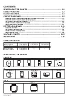
Page 105: ...CKET PWB PATTERN 2 21 FRONT CONTROL PWB PATTERN 2 22 BASS PWB PATTERN 2 23 VOLTAGE CHARTS 2 25 WAVEFORMS 2 26 USING P W BOARD IC BOTTOM VIEW FRONT VIEW TOP VIEW 1 N N 1 OUT E IN IN OUT E 1 N TOP VIEW N 1 N N N 1 N CHIP IC TRANSISTOR BOTTOM VIEW FRONT VIEW TOP VIEW CHIP TR E C B E C B C B E B G E S C D E C B E C B PWB ASS Y name AV 2986ME AV 29MS26 AV 29MX76 G MAIN P W BOARD SCW 1926A H2 SCW 1927A ...

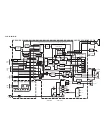
Page 106: ... SCALER DRAM A D CONVERT OVER SAMPLE I2C RGB MATRIX D A CONVERT IC301 PIP CONTROL SYNC PROC V Y U 29 30 SIF IN VIF IN SIF DETECT VIDEO IDENT AUDIO CONTROL COMB FILTER Y DELAY ADJ COLOUR DEMOD SYNC SEP H DRIVE VIF DETECT AGC AFT SOUND TRAP TELETEXT DECODER DIGITAL SIGNAL PROCESS PEAKING SCAN VELOCITY MOD U V DELAY RGB MATRIX GAMMA AUDIO SELECT VIDEO SELECT I O PORT AUDIO SELECT G3 Y B3 PB R3 PR V2 ...

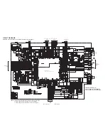
Page 107: ...964 Y963 IC702 R748 C616 R739 R481 C612 C611 Y944 D611 R625 R788 Y605 Y943 L702 L701 C744 C745 R785 R784 R484 R768 R774 R773 R775 C741 C799 D982 Q613 C798 D706 D981 C790 R488 D101 C796 Q609 Q610 Q611 C661 R632 W A1 R786 Y604 D711 D712 D481 C795 R720 W A R730 1 2K 1 22 10 X X 0047 1 1 1 1 2K 27K 4 7K 1 1 1 1 1 4 7K 0 4 5 3 22 33 50 15K 3 9K 220 01 220 470 10 1 X 01 10 50 18p 1K X 56p X 75 X X 75 X ...

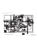
Page 108: ... R522 CN00D Y909 Y910 R528 D520 Q521 C966 Q921 R575 R530 C520 R461 R462 C531 L521 R525 R524 C523 C925 C926 R928 C924 D929 C904 D930 C991 IC951 K952 C956 D953 R533 C958 D555 C582 R571 R572 C553 D901 R552 C530 R551 R574 C532 C571 C554 C551 D975 D951 C527 R521 R520 D552 D521 D522 D952 CP952 C957 C992 C967 K951 CN00W L522 C552 C_MUTE P_ON OFF NECK D977 C901 C526 HFB ABL C524 C902 H_DRIVE R924 C525 D93...

Page 109: ...L306 R787 C316 D710 Q981 R772 Y964 Y963 IC702 R748 C616 R739 R481 C612 C611 Y944 D611 R625 R788 Y605 Y943 L702 L701 C744 C745 R785 R784 R484 R768 R774 R773 R775 C741 C799 D982 Q613 C798 D706 D981 C790 R488 D101 C796 Q609 Q610 Q611 C661 R632 W A1 R786 Y604 D711 D712 D481 C794 R720 W A R730 1 2K 1 22 10 0 1 16 0 1 16 0047 1 1 1 1 2K 27K X 1 X X X 1 4 7K 0 4 5 3 22 33 50 15K 3 9K 220 01 220 470 10 1 ...

Page 110: ...984 Y914 Y913 GND GND Q522 C955 CP955 C960 GND GND C962 K105 Y909 Y910 R522 CN00D Y909 Y910 R528 D520 Q521 C966 Q921 R575 R530 C520 R461 R462 C531 L521 R525 R524 C523 C925 C926 R928 C924 D929 C904 D930 C991 IC951 K952 C956 D953 R533 C958 D555 C582 R571 R572 C553 D901 R552 C530 R551 R574 C532 C571 C554 C551 D975 D951 C527 R521 R520 D552 D521 D522 D952 CP952 C957 C992 C967 K951 CN00W L522 C552 C_MUT...

Page 111: ...2 CN0E2 C207 C210 R373 TP E R377 R375 D372 R376 R203 C358 C371 D371 CN0VM IC351 D363 SG353 SK351 SG351 R374 SG352 SK351 CN0SC SG354 CN0VM Y354 Y353 R201 R204 R205 C208 R369 C209 K201 R202 R206 R350 CN00U R369 C203 Q201 Q202 R355 R356 R357 C220 D354 D355 D356 C353 Q374 L351 D357 K208 D350 C204 47 2 7K 1 5K 100 0 1 2K 1 5K 1 5K 1 5K 100 100 220 16 X 220 100 1000p 150 1 5K 56K 56K 10 X X X X 39 15K 3...

Page 112: ... F901 R803 S803 S804 R901 R802 R302 Y806 Y805 CN00S LF901 C807 C806 R816 C802 R815 R806 IC801 R804 R801 D801 J803 J804 J802 J801 R807 C803 CN002 R814 R809 CN0PW C901 VA901 CN00W Y801 C804 S901 R808 R813 R812 IC301 CNDEG DEG COIL RY901 TH901 C902 R302 R810 D956 Q955 R960 R961 D957 C965 CN001 R601 R604 R602 R603 D803 Y904 Y902 Y901 Y804 K801 Y903 C301 Y802 Y803 LC801 0 1 50 X 470 47 X 0 1500p 1500p ...

Page 113: ...88 C685 C686 C690 C691 GND IC671 R681 R680 R679 R678 R677 R675 R673 R674 R676 C682 C681 C680 C678 C676 C675 C674 C673 C672 L671 R672 R671 X671 C679 C684 C677 C671 C683 R672 CN00M R671 220 220 1 1 68p 68p X X 10 4 7K 4 7K 10K 12K 12K 100K 33P 33P 0 1 015 33P 33P 33P 33P 33P 5 6K 5 6K 100 16 10 50 1 50 47 50 0 1 c21257001a 001 1 1 BASS PWB CIRCUIT DIAGRAM SHEET 7 MAIN PWB ASS Y 1 2 SHEET1 3 CN00M ...

Page 114: ...R766 C742 C704 R712 R713 W047 W049 W050 W052 W063 W064 W065 W066 W067 W068 25 C7 C726 W055 C727 R715 C728 C7 29 C732 E W023 CP956 W056 W059 E W060 W061 W069 W070 C735 C736 C744 D702 C745 C737 D703 C738 C739 R716 R717 R718 W101 R719 D708 W072 W073 W074 W034 CN00C C743 W029 W075 R704 W025 W076 W077 W080 W082 C730 C731 C734 R315 Q981 C993 R760 R316 CN00M R317 W083 R632 C309 C308 L303 C313 C312 L306 C...

Page 115: ...9 R360 Q371 W003 W004 W005 W006 W008 R369 R221 R224 R228 R229 R232 SG351 SG352 SK351 SG353 R215 FR201 C352 C208 C210 C219 C214 C216 Q372 Q373 CN00T C353 Q374 R371 C205 R208 C209 C217 C218 R351 R352 R353 R201 C212 C215 C207 C220 R372 R354 C201 W010 W018 W013 W015 W016 R373 W017 CN0E1 D350 R375 SG354 D357 CN00U R355 R376 CN0SC R377 W020 W011 K201 K202 K203 K204 HS351 R356 R357 D371 D372 D354 C203 R2...

Page 116: ...679 IC671 C685 C683 C690 C686 C688 C689 C691 CN00M L671 R678 R677 C677 C676 C6 75 C6 74 C673 C672 R676 X671 R6 74 R673 R672 R671 C671 R675 84 C6 R679 C6 78 C679 C680 C681 C682 R680 R681 R6 82 R683 TOP TOP BASS PWB PATTERN PARTS SIDE BASS PWB PATTERN SOLDER SIDE ...

Page 117: ...8 2 0 109 1 9 110 3 2 111 1 7 112 0 113 0 114 3 1 115 3 1 116 2 6 117 1 9 118 1 9 119 3 1 120 3 0 121 0 122 3 1 123 0 124 1 9 125 0 126 3 2 127 3 1 128 3 1 IC702 1 0 2 0 3 0 4 0 5 3 2 6 3 2 7 0 8 3 2 IC921 1 125 4 2 NC 3 0 4 19 7 5 4 0 6 1 7 7 0 3 IC951 1 135 1 2 21 9 3 0 IC971 1 3 2 2 0 2 3 0 4 1 9 5 3 7 6 0 7 6 1 IC972 1 6 7 2 0 3 3 1 4 IC973 1 16 4 2 11 8 3 0 4 3 1 IC975 1 7 5 2 4 9 3 0 4 3 2 Q...

Page 118: ... No YA447 Display Category 12 3 chome Moriya cho kanagawa ku Yokohama city kanagawa prefecture 221 8528 Japan Victor Company of Japan Limited VPT Printed in Japan ...

Reviews: