background image

No. 51858

AV-21D10/AV-21DM10

AV-2134EE/AV-21DTG2

9

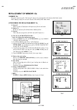
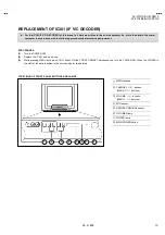
REPLACEMENT OF MEMORY ICs

1. MEMORY ICs

This model uses memory ICs. This memory IC data are for proper operation of the video and deflection circuits.

When replacing memory ICs, be sure to use ICs written with the initial values of data.

2. PROCEDURE FOR REPLACING MEMORY ICs

(1) Power off

Switch the power off and disconnect the power plug from the wall outlet.

(2) Replace ICs

Be sure to use memory ICs written with the initial data values.

(3) Power on

Connect the power plug into the wall outlet and switch the power on.

(4)  Check and set SYSTEM CONSTANT SET

It must not adjust without adjustment signals.

1) Press the 

DISPLAY

 key and the 

PICTURE


MODE

 key of the REMOTE

CONTROL UNIT simultaneously.

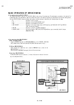
2)  The SERVICE MENU screen of Fig. 1 will be displayed.

3)  While the SERVICE MENU is displayed, again press the 

DISPLAY

 key and

PICTURE


MODE

 key simultaneously, and the SYSTEM CONSTANT SET

screen of Fig. 2 will be displayed.

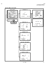
1)  Check the setting values of the SYSTEM CONSTANT SET of Table 1 If the

value is different, select the setting item with the 

MENU


/

key, and set

the correct value with the 

MENU

 - / + key.

5) Press the 

DISPLAY

 key twice, and return to the normal screen.

(5)  Receive channel of setting

Refer to the 

OPERATING INSTRUCTIONS

 and set the receive channels

(channels preset) as described

(6) User Setting

Check the user setting value of Table 2, and if setting value is different, set

the correct value.

For setting, refer to the 

OPERATING INSTRUCTIONS

.

(7)  Setting of SERVICE MENU

Verify the setting items of the SERVICE MENU of Table 3, and reset where

necessary.

For setting, refer to the 

SERVICE ADJUSTMENTS

.

  NOTE


Both

 MENU -/+ Key and MENU 

  /  key have the same functions.

SERVICE MENU

1.IF                  2.V/C
3.DEF              4.VSM PRESET
5.PRESET
6.TURBO TIMER OFF

1-6 SELECT                   DISP : EXIT

******

******

******

***********

*****

*****

*****

**

**

**

**

.

***

***

***

***

***   **   **

***   **   **

***   **   **

***   **   ****   ***

**   ***

**   ***

**   ***

Fig.1

Fig.2

SYSTEM CONSTANT-

COLOUR

COLOUR

COLOUR

COLOUR

: *****

*****

*****

*****

BILINGUAL

BILINGUAL

BILINGUAL

BILINGUAL

: ***

: ***

: ***

: *** 


TUNER

TUNER

TUNER

TUNER

: **

**

**

**

ECO SENSOR

ECO SENSOR

ECO SENSOR

ECO SENSOR

:  YES

:  YES

:  YES

:  YES

LANGUAGE

LANGUAGE

LANGUAGE

LANGUAGE

:  E/R/A/F

:  E/R/A/F

:  E/R/A/F

:  E/R/A/F

: SELECT
: OPERATE

DISP : EXIT

   SYSTEM CONSTANT SET

       1

SYSTEM CONSTANT-

B/B SOUND

:  NO

LOCK

:  180

COLOUR AUTO :  YES
QSS

:  MINT

ALC

:  NO

TEXT RATE

:  20

   SYSTEM CONSTANT SET        2

:SEL

DISP:EXIT

:OPE

SYSTEM CONSTANT-

AMP TUNER

AMP TUNER

AMP TUNER

AMP TUNER

:  YES

:  YES

:  YES

:  YES

VNR

VNR

VNR

VNR

:  NO

:  NO

:  NO

:  NO

TEXT TABLE

TEXT TABLE

TEXT TABLE

TEXT TABLE

:

::

:


***

***

***

***

   SYSTEM CONSTANT SET        3

DISP:EXIT

:SEL

:OPE

KEY ASSIGNMENT OF REMOTE CONTROL UNIT

MENU

/

 key

MENU

/

key

DISPLAY key

PICTURE

MODE key

 NUMBERS

key

Summary of Contents for AV-2134EE

Page 1: ...21D10 AU AV 21DM10 AV 21DM10 A AV 2134EE AV 21DTG2 A CONTENTS SPECIFICATIONS 2 SAFETY PRECAUTIONS 3 FEATURES 4 FUNCTIONS 5 MAIN DIFFERENCE LIST 6 SPECIFIC SERVICE INSTRUCTIONS 7 SERVICE ADJUSTMENTS 14 PARTS LIST 31 OPERATING INSTRUCTIONS STANDARD CIRCUIT DIAGRAM 2 1 SERVICE MANUAL COLOUR TELEVISION BASIC CHASSIS CG ...

Page 2: ... key twice and return to the normal screen 5 Receive channel of setting Refer to the OPERATING INSTRUCTIONS and set the receive channels channels preset as described 6 User Setting Check the user setting value of Table 2 and if setting value is different set the correct value For setting refer to the OPERATING INSTRUCTIONS 7 Setting of SERVICE MENU Verify the setting items of the SERVICE MENU of T...

Page 3: ...0 AMP TUNER NO VNR YES TEXT TABLE CYL Table 1 USER SETTING VALUES Setting item Setting value Setting item Setting value MAIN POWER SW OFF PICTURE MODE VSM BRIGHT SUB POWER ON LANGUAGE ENGLISH ENG CHANNEL POSITION 1 POSITION CHANNEL PRESET Refer to OPERATING INSTRUCTION VOLUME About 10 ECO SENSOR OFF TV VIDEO TV VNR OFF ON SCREEN DISPLAY POSITION INDICATION AUTO SHUTOFF OFF COLOUR SYSTEM AUTO PAL O...

Page 4: ...TSC 3 58 NTSC 4 43 RED GREEN 1 CUT OFF BLUE 128 127 50 RED 2 DRIVE BLUE 128 127 0 3 BRIGHT 127 127 0 4 CONT 63 63 0 5 COLOUR 63 63 0 TV 0 0 6 TINT VIDEO 63 63 8 0 7 SECAM BL ADJ 31 31 0 TV 8 Fixed 8 SHARP Do Not Adj VIDEO 32 31 15 Fixed 3 DEFLECTION Initial setting value Setting item Variable range fv 50Hz MODE fv 60Hz MODE 1 VER POSITION 04 03 1 3 2 HOR POSITION 16 15 3 3 3 VER HEIGHT 64 63 35 1 ...

Page 5: ...0 0 0 0 3 ABL 1 1 1 1 4 GAMMA 0 0 0 0 TV 0 2 2 3 5 Y DELAY TIME VIDEO 0 2 0 2 6 BLACK EXP START 3 3 3 3 TV 1 1 0 0 7 C BPF VIDEO 1 1 1 1 8 CW SCP 0 0 0 0 9 VIF DET LEVEL 0 0 0 0 11 IF AGC MIN 0 0 0 0 12 VIF AGC 0 0 0 0 13 VIF PMOD 0 0 0 0 19 VNR 15 15 15 15 20 RGB LIM 1 1 1 1 21 RGB LIMIT LEVEL 2 2 2 2 23 TEXT H POSITION 3 3 3 3 24 READ DATA Sound System Do Not Adjust Setting item B G I D K M 10 S...

Page 6: ...rting adjustment PROCEDURES 1 Turn the POWER OFF 2 Replace the IC301 with a new one 3 While pressing MENU button and VOL button ON the FRONT CABINET simultaneously turn the POWER ON When the POWER is turned ON the data is written in the micro computer immediately LOCATIONS OF FRONT PANEL BUTTONS AND LAMPS MENU buttons CHANNEL buttons MENU buttons VOLUME buttons MENU buttons ECO sensor REMOTE CONTR...

Page 7: ...less otherwise specified prepare the most suitable reception or input signal for adjustment 6 Never touch any adjustment setting value which are not specified in the list for this adjustment 7 Preparation for adjustment Unless otherwise specified in the adjustment instructions preset the following functions with the REMOTE CONTROL UNIT User mode position PICTURE MODE VSM BRIGHT VNR OFF COLOUR BRIG...

Page 8: ...nd BRIGHT VSM Video Status Memory 5 PRESET Adjustment of the RF circuit Do not adjust 6 TURBO TIMER For quick setting the TIMER count value adjustable not only by minuets but also by second Should be OFF Key operation of the SERVICE MENU Enter to SERVICE MENU Press the DISPLAY key and the PICTURE MODE key of the REMOTE CONTROL UNIT simultaneously Then enter the SERVICE MENU mode as shown in Fig 1 ...

Page 9: ...g items DISPLAY Key When this is pressed twice you will return to the SERVICE MENU 2 V C 3 DEF and 4 VSM PRESET 2 4Key Select one from 2 V C 3 DEF and 4 VSM PRESET MENU Key Select setting items MENU Adjust the setting values of the setting items DISPLAY Key When this is pressed return to the SERVICE MENU 6 TURBO TIMER By pressing the 6 key you can change the ON or OFF should be OFF Should be OFF I...

Page 10: ...NT UHF AGC TAKE OVER OPERATE DISP EXIT 6 TURBO TIMER ON OFF By pressing 6 key SERVICE MENU 1 IF 2 V C 3 DEF 4 VSM PRESET 5 PRESET 6 TURBO TIMER OFF 1 6 SELECT DISP EXIT OFF V C PAL 1 CUTOFF OPERATE DISP EXIT R G B 50Hz SUB MENU 2 V C SELECT DEF OPERATE DISP EXIT SUB MENU 3 DEF SELECT 50Hz 1 VER POSITION PAL PRESET 1 C TRAP FIX OPERATE DISP EXIT 50Hz SUB MENU 5 PRESET SELECT B G PAL BRIGHT TINT COL...

Page 11: ...B1 IC421 VERT OUT Q522 H OUT DY V DY H DEF YOKE H OUT V OUT H OUT V OUT 42 46 SCL SDA POWER SW IN OUT AC IN Q103 SW HEAD PHONE CF901 30 31 32 SAW EXT RGB TU001 TUNER IF T921 SW TRANSF IC921 POWER REG PC921 VOLTAGE FEEDBACK IC941 ERROR AMP IC971 9V REG REG D901 RECT R G B V01 CRT CRT SOCKET PWB RGB DRV ECO REMOCON KEY IND VIDEO AUDIO T522 HVT FOCUS SCREEN EHV B1 SP 18 19 3 58 OTH 25 37 38 6 7 8 VID...

Page 12: ...3V 0 6V 4 2V 4 1V 9V 4 6V 4 2V 8 5V 4 9V 0V 3 3V 6 2V 4 2V 3 4V 3 6V 3 9V 3 2V 2 7V 3 8V 9V 4 1V 2 8V 3 1V 3 1V 3 2V 9V 4 9V 4 9V 2 2V 9V 3 4V 2 9V 3 2V 3 6V 1 8V 1 8V 2 7V 1 5V 4 2V 4 3V 4 9V 32 6V 0V 1 8V 3 8 V 2 4V 0 2V 0 1V 0 2V 0V 2 4V 0 5V 3 3V 0V 3 3V 4V 0 3V 0 8V 0 1V 0 5V 0V 2 4V 0 7V 3 3V 0V 2 4V 0 1 V 0V 4V 4V 1 7V 0 1V 0 1V 4 1V 0V 2 2V 4 9V 0 5V 1 5V 0V 3 7V 4 9V 3 3V 4 9V 2 4V 4 9V 4...

Page 13: ...IN PWB SCG 1027A H2 SCG 1281A H2 AV 2134EE AV 21D10 AU 1 2 CRT SOCKET PWB SCG 1025A H2 SCG 1026A H2 AV 21DM10 AV 21DM10 A AV 21D10 1 2 Within MAIN PWB CRT COCKET SCG 1026A H2 AV 21D10 SCG 1023A H2 AV 21DTG2 A SCG 1025A H2 AV 21DM10 AV 21DM10 A SCG 1023A H2 AV 21DTG2 A SCG 1027A H2 SCG 1281A H2 AV 2134EE AV 21D10 AU PICTURE TUBE H2 H2 H2 H2 H2 QMPR340 165 K2 AV 21D10 AV 21DM10 AV 2134EE QMP2980 185...

Reviews: