background image

4

Preparation

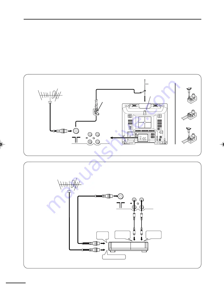
3 Connecting the aerial and external devices

• For further details, refer to the manuals provided with the devices you are connecting.
• Connecting cables are not supplied.
• The front and rear AUDIO/VIDEO input jacks are directly connected so that input to either jack

is output through both. You cannot provide input to both the front and rear jacks at the same
time. Disconnect one input, or use one of the jacks as an output jack only (for monitoring or
recording).

Connecting the aerial and VCR

Connecting the aerial

• Illustration of AV-14F116

• Illustration of AV-14F116.

Connecting the aerial and VCR


!

VIDEO

AUDIO

IN

OUT

To RF 
output

To video 
output

To aerial input

To audio 
output

3

2

VCR

VHF/UHF outdoor aerial

1

* AV-14F116 only.

 GGT0111-001A-H_P02-05

18/4/06, 5:41 PM

4

Summary of Contents for AV-14F116

Page 1: ...tor Company of Japan Limited No YA439 2006 8 COLOUR TELEVISION YA439 2006 8 AV 14F116 B TABLE OF CONTENTS 1 PRECAUTION 1 3 2 SPECIFIC SERVICE INSTRUCTIONS 1 4 3 DISASSEMBLY 1 5 4 ADJUSTMENT 1 11 5 TROUBLESHOOTING 1 24 BASIC CHASSIS CG4 ...

Page 2: ... 5MHz 6 5 MHz D K Colour Sub Carrier PAL SECAM NTSC 4 43 MHz 4 40625 MHz 4 25 MHz 3 58 MHz 4 43 MHz Power Input AC220 V to AC240 V 50 Hz 60Hz Power Consumption 68 W Max 47W Avg Picture Tube Visible size 34 cm measured diagonally H 28 7 cm V 21 7 cm High Voltage 22 5 kV 1 5kV at zero beam current Speaker 5 cm 9 cm Oval type 2 Audio Power Output 3 W monaural Aerial Input Terminal 75 Ω unbalanced coa...

Page 3: ...lacements or alternatives approved by the manufacturer of the complete product 7 Do not check high voltage by drawing an arc Use a high voltage meter or a high voltage probe with a VTVM Discharge the picture tube before attempting meter connection by connecting a clip lead to the ground frame and connecting the other end of the lead through a 10kΩ 2W resistor to the anode button 8 When service is ...

Page 4: ...L2 O Clock for Inter IC contorl For main memory 24 LOCK Not used 4 BUS_FREE Not used 25 3 58 OTH Not used 5 NC Not used 26 4 5 OTH Not used 6 KEY1 I Key scan for front key Menu CH 27 H_SYNC I Horizontal sync 7 KEY2 I Key scan for front key Vol 28 I II Not used 8 ECO IN Not used 29 OSD_Ys O Ys blanking for OSD 9 AFT I AFT voltage for tuner 30 OSD_B O Blue for OSD 10 LED POW Not used 31 OSD_G O Gree...

Page 5: ... REMOVING THE SPEAKER Remove the REAR COVER 1 Remove the 4 screws D as shown in Fig 1 2 Follow the same steps when removing the other hand SPEAKER 3 1 4 CHECKING THE MAIN PW BOARD To check the back side of the MAIN PWB 1 Pull out the MAIN PWB Refer to REMOVING THE MAIN PW BOARD 2 Erect the MAIN PWB vertically so that you can easily check its back side CAUTIONS Before turning on power make sure tha...

Page 6: ...1 6 No YA439 Fig 1 FRONT CABINET SPEAKER REAR COVER MAIN PWB SPEAKER CRT SOCKET PWB Within MAIN PWB A C B D D POWER CORD ...

Page 7: ...lue is different select the setting item with the MENU key and set the correct value with the MENU key 5 Press the DISPLAY key twice and return to the normal screen 5 Receiving channel setting Refer to the OPERATING INSTRUCTIONS and set the receive channels Channels Preset as described 6 User settings Check the user setting items according to the given in page later Where these do not agree refer ...

Page 8: ...OLOUR SYSTEM PAL SOUND SYSTEM B G Setting item Setting position INPUT TV ON TIMER PR1 0 00 VNR OFF Setting item Setting position AUTO SHUTOFF OFF CHILD LOCK OFF BLUE BACK OFF Setting item Setting position SETUP TOUR ON LANGUAGE THAI Setting item Setting position BRIGHT STANDARD SOFT TINT 15 15 15 COLOUR 15 15 15 BRIGHT 15 15 15 CONT 30 15 13 SHARP 15 15 12 Setting item Setting value COLOUR TRIPLE ...

Page 9: ...NT PANEL BUTTONS Setting item Setting value Setting item Setting value 2 V C 1 CUT OFF 2 DRIVE 3 BRIGHT 4 CONT 5 COLOUR 6 TINT 7 SECAM BL ADJUST 8 SHARP Do not adjust 9 AMP T SHARP Do not adjust 5 PRESET Do not adjust Colour System 1 C TRAP FIX 2 SHARP PEAK 3 ABL 4 GAMMA 5 Y DELAY TIME 6 BLACK EXP START 7 C BPF 8 CW SCP 9 VIF DET LEVEL 11 IF AGC MIN 12 VIF AGC 13 VIF PMOD 19 VNR 20 RGB LIM 21 RGB ...

Page 10: ...he tweezers and remove the chip part Transistors diodes variable resistors etc 1 Apply extra solder to each lead 2 As shown in the figure push the part with tweezers and alternately melt the solder at each lead Shift and remove the chip part NOTE After removing the part remove remaining solder from the pattern 2 How to install Chip parts Resistors capacitors etc 1 Apply solder to the pattern as in...

Page 11: ...istors transformers and condensers not shown in the adjustment items of this service adjustment 4 2 PRESET SETTING BEFORE ADJUSTMENT Unless otherwise specified in the adjustment items preset the following functions with the REMOTE CONTROL UNIT 4 3 MEASURING INSTRUMENT AND FIXTURES 1 DC voltmeter or digital voltmeter 2 Oscilloscope 3 Signal generator Pattern generator PAL SECAM NTSC 4 Remote contro...

Page 12: ...n TP 91 B1 2Pin NC 3Pin X ray1 4Pin X ray2 5Pin TP E HVT S1 HV U IC301 MEMORY IC IC702 IC701 F901 DEG TU001 FRONT TOP MAIN PWB CRT SOCKET PWB SOLDER SIDE E1 U T PW UPPER FOCUS LOWER SCREEN TP 47G R TP 47B TP E T CRT EARTH WIRE BRAIDED ASS Y 5 1 ...

Page 13: ... MENU When complete the adjustment work press the DISPLAY key to return to the SERVICE MENU And then press the DISPLAY key again to return to the normal screen 4 6 6 SELECTION OF SUB MENU SCREEN Press one of 1 to 5 keys of the REMOTE CONTROL UNIT and select the SUB MENU SCREEN form the SERVICE MENU 1 IF Adjustment of the IF circuits 2 V C Adjustment of the VIDEO circuit 3 DEF Adjustment of the DEF...

Page 14: ...o the SERVICE MENU 1 1 key Select 1 IF 2 2 key Select 2 DELAY POINT 3 MENU keys Set adjust the setting values of the setting items 4 DISPLAY key When this is pressed twice you will return to the SERVICE MENU 1 2 to 4 keys Select one from 2 V C 3 DEF and 4 VSM PRESET 2 MENU keys Select setting items 3 MENU keys Adjust the values of the items 4 DISPLAY key When this is pressed you will return to the...

Page 15: ...T UHF AGC TAKE OVER OPERATE DISP EXIT 6 SETUP TOUR OFF BRIGHT TINT COLOUR BRIGHT CONT SHARP OPERATE DISP EXIT 4 VSM PRESET SELECT DEF AUTO OPERATE DISP EXIT 3 DEF SELECT 50Hz 1 VER POSITION V C PAL 1 CUTOFF R G B OPERATE DISP EXIT 50Hz 2 V C SELECT PRESET AUTO 1 C TRAP FIX OPERATE DISP EXIT 50Hz B G 5 PRESET SELECT SERVICE MENU 1 IF 2 V C 3 DEF 4 VSM PRESET 5 PRESET 6 SETUP TOUR OFF 1 6 SELECT DIS...

Page 16: ...50 BLUE 128 127 50 50 50 50 2 DRIVE RED 128 127 0 0 0 0 BLUE 128 127 0 0 0 0 3 BRIGHT 128 127 0 0 0 0 4 CONT 63 63 0 0 0 0 5 COLOUR 63 63 0 0 0 0 6 TINT TV 63 63 0 0 VIDEO 63 63 0 0 7 SECAM BL ADJUST 31 31 0 0 0 0 8 SHARP Do not adjust TV 31 31 17 Fixed 17 Fixed 17 Fixed 17 Fixed VIDEO 31 31 10 Fixed 10 Fixed 10 Fixed 10 Fixed Setting item Variable range Initial setting value fv 50Hz fv 60Hz 1 VER...

Page 17: ...ELAY TIME TV 0 3 0 2 2 3 VIDEO 0 3 0 2 0 2 6 BLACK EXP START 0 3 3 3 3 3 7 C BPF TV 0 1 1 1 0 0 VIDEO 0 1 1 1 1 1 8 CW SCP 0 1 0 0 0 0 9 VIF DET LEVEL 63 63 0 0 0 0 11 IF AGC MIN 0 1 0 0 0 0 12 VIF AGC 0 1 0 0 0 0 13 VIF PMOD 0 1 0 0 0 0 19 VNR 0 63 15 15 15 15 20 RGB LIM 0 1 1 1 1 1 21 RGB LIMIT LEVEL 0 7 2 2 2 2 23 TEXT H POSITION 16 15 3 3 3 3 24 READ DATA Setting item Variable range Initial se...

Page 18: ...rectly calibrated 1 Receive any broadcast 2 Select 1 IF from the SERVICE MENU 3 Select 1 VCO 4 Select VCO ADJUST with MENU key 5 Press MENU keys until the colour of the characters TOO HIGH changes blue to yellow Then gradually press the MENU keys until the TOO LOW changes yellow At this time confirm that the value of VCO ADJUST is near 00 6 Select AFT ADJUST with MENU key 7 Press MENU keys until t...

Page 19: ...re are no irregularities Item Measuring instrument Test point Adjustment part Description DELAY POINT UHF AGC TAKE OVER OPERATE DISP EXIT Setting Item Variable range Initial setting value 45 35 DELAY POINT AGC TAKE OVER 0 127 NTSC3 58 OTHER Item Measuring instrument Test point Adjustment part Description FOCUS Signal generator FOCUS VR In HVT 1 Receive a crosshatch signal 2 While watching the scre...

Page 20: ...ION 4 Set the initial setting value of 1 VER POSITION 5 Adjust 1 VER POSITION to make the vertical centre fall on the display centre 6 Select 3 VER HEIGHT 7 Set the initial setting value of 3 VER HEIGHT 8 Adjust 3 VER HEIGHT to make the vertical screen size be 92 of the picture size Fig 1 H POSITION Signal generator Remote control unit 3 DEF 2 HOR POSITION 1 Receive a circle pattern signal 2 Selec...

Page 21: ...the 2 key to turn off the single horizontal line 10 Press the DISPLAY key twice to return to the nor mal screen WHITE BALANCE HIGH LIGHT Signal generator Remote control unit 2 V C 2 DRIVE R 2 DRIVE B 1 Receive a black and white signal colour off 2 Select 2 V C from the SERVICE MENU 3 Select 2 DRIVE 4 Set the initial setting value of 2 DRIVE 5 Adjust the screen until it becomes white using the 4 6 ...

Page 22: ...LOUR PAL SECAM NTSC Method of adjustment using measuring instrument PAL COLOUR 1 Receive a PAL full field colour bar signal 75 white 2 Select 2 V C from the SERVICE MENU 3 Select 5 COLOUR 4 Set the initial setting value of 5 COLOUR 5 Connect the oscilloscope to TP 47G R and TP E 6 Adjust PAL COLOUR to bring the value of A in the voltage table SECAM COLOUR 1 Receive a SECAM full field colour bar si...

Page 23: ...ect the oscilloscope to TP 47G R and TP E 6 Adjust NTSC 3 58 TINT to bring the value of B in the voltage table in the left NTSC 4 43 TINT 1 When NTSC 3 58 is set NTSC 4 43 will be automatically set at the respective values SECAM BLACK OFFSET Signal generator Remote control unit 2 V C 7 SECAM BL ADJUST 1 Input a SECAM full field colour bar signal 2 Select 2 V C from the SERVICE MENU 3 Select 7 SECA...

Page 24: ...ct 4 VSM PRESET from the SERVICE MENU 2 Set the PICTURE MODE to BRIGHT 3 Select TINT 4 Set the initial setting value of TINT as shown in the below table 5 Select COLOUR to SHARP in turn and set the values 6 Respectively select the SOFT and STANDARD Make similar adjustment as same step as above TINT COLOUR BRIGHT CONT SHARP VSM PRESET VSM PRESET Setting item BRIGHT 15 15 15 30 15 STANDARD SOFT 15 1...

Page 25: ... No YA439 1 25 ...

Page 26: ... No YA439 Display Category 12 3 chome Moriya cho Kanagawa ku Yokohama city Kanagawa prefecture 221 8528 Japan Victor Company of Japan Limited VPT Printed in Japan ...

Page 27: ...pacitor MF R Metal Film Resistor MF CAP Metalized Film Capacitor MG R Metal Glazed Resistor MM CAP Metalized Mylar Capacitor MP R Metal Plate Resistor MP CAP Metalized Polystyrol Capacitor OM R Metal Oxide Film Resistor PP CAP Polypropylene Capacitor CMF R Coating Metal Film Resistor PS CAP Polystyrol Capacitor UNF R Non Flammable Resistor TF CAP Thin Film Capacitor CH V R Chip Variable Resistor M...

Page 28: ... PICTURE TUBE Inc DEF YOKE PC MAGNET L01 QQW0171 001 DEG COIL T522 QQH0168 001 FB TRANSF 1 LC10831 046A H FRONT CABINET 2 CM46880 002 H JVC MARK 3 LC30617 001C H E E WINDOW 4 LC30616 004A H POWER KNOB 5 CM35235 003 H SPRING 6 LC20292 004A H CONTROL KNOB 7 LC30618 001B H LED LENS 11 QYSBSFG4016ZA TAP SCREW M4 x 16mm x4 12 QYSBSF3010ZA TAP SCREW M3 x 10mm 13 QYSBSFG4012MA TAP SCREW M4 x 12mm 14 CM12...

Page 29: ... No YA439 3 3 EXPLODED VIEW 1 RATING LABEL 1 2 3 4 5 6 7 11 13 12 14 15 16 20 21 20 21 T522 V01 L01 19 18 CRT SOCKET PWB Within MAIN PWB 30 30 MAIN PWB 17 ...

Page 30: ...R 0 22uF 50V J C119 QETN1HM 474Z E CAPACITOR 0 47uF 50V M C120 NDC31HJ 121X C CAPACITOR 120pF 50V J C121 NCB31HK 103X C CAPACITOR 0 01uF 50V K C122 NCB31HK 103X C CAPACITOR 0 01uF 50V K C161 NCB31HK 103X C CAPACITOR 0 01uF 50V K C162 NCB31HK 152X C CAPACITOR 1500pF 50V K C164 NCB31HK 103X C CAPACITOR 0 01uF 50V K C165 NCB31HK 103X C CAPACITOR 0 01uF 50V K C166 NCB31HK 104X C CAPACITOR 0 1uF 50V K ...

Page 31: ...4 7kΩ 1 16W J R303 NRSA63J 101X MG RESISTOR 100Ω 1 16W J Ref No Part No Part Name Description Local R304 NRSA63J 101X MG RESISTOR 100Ω 1 16W J R305 NRSA63J 101X MG RESISTOR 100Ω 1 16W J R306 NRSA63J 0R0X MG RESISTOR 0Ω 1 16W J R307 NRSA63J 122X MG RESISTOR 1 2kΩ 1 16W J R308 NRSA63J 182X MG RESISTOR 1 8kΩ 1 16W J R312 NRSA63J 0R0X MG RESISTOR 0Ω 1 16W J R313 NRSA63J 102X MG RESISTOR 1kΩ 1 16W J R3...

Page 32: ...W J R906 QRL029J 104 OMF RESISTOR 100kΩ 2W J R921 QRE121J 1R8Y C RESISTOR 1 8Ω 1 2W J R922 QRE121J 221Y C RESISTOR 220Ω 1 2W J R923 QRZ0237 R18 UNF WW RESISTOR 0 18Ω 3W J R924 NRSA63J 154X MG RESISTOR 150kΩ 1 16W J R925 NRSA63J 105X MG RESISTOR 1MΩ 1 16W J R928 QRL039J 683 OMF RESISTOR 68kΩ 3W J R933 QRE121J 4R7Y C RESISTOR 4 7Ω 1 2W J R934 NRSA63J 683X MG RESISTOR 68kΩ 1 16W J R935 QRE121J 392Y C...

Page 33: ...0 BATTERY COVER Ref No Part No Part Name Description Local 1 LC12622 001A H PACKING CASE 2 LC10833 002B H CUSHION ASS Y 4pcs in 1set 3 GG30097 002A H POLY BAG 4 GG30096 001A H POLY BAG 5 BATTERY AA R6 1 5V x2 6 GGT0111 001A H INST BOOK 7 QAL0900 001 ROD ANTENNA 8 ATEAB001 00A MATCHING BOX 9 RM C1121 1H REMOCON UNIT 9 2 3 2 1 4 5 6 7 8 ...

Page 34: ...eries 3 3 Connecting the aerial and external devices 4 4 Connecting the power cord 6 5 SETUP TOUR 6 Basic operation 7 Remote control buttons and functions 8 PICTURE MODE button 8 COLOUR SYSTEM button 8 SOUND SYSTEM button 8 I II button 8 DISPLAY button 9 RETURN button 9 CHANNEL SCAN button 9 MUTING button 9 OFF TIMER button 9 Using the TV s menus 10 Basic operation 10 ON TIMER 11 INPUT 11 VNR 12 A...

Page 35: ...n the minimum distances shown in the diagram Do not allow objects or liquid into the cabinet openings In the event of a fault unplug the TV and call a service technician Do not attempt to repair it by yourself or remove the rear cover The surface of the TV screen is easily damaged Be very careful with it when handling the TV Should the TV screen become soiled wipe it with a soft dry cloth Never ru...

Page 36: ...ectly insert two batteries observing the and polarities and inserting the end first CAUTION Follow the cautions printed on the batteries Notes Use AA R6 UM 3 dry cell batteries If the remote control does not work properly fit new batteries The supplied batteries are for testing not regular use ...

Page 37: ...ither jack is output through both You cannot provide input to both the front and rear jacks at the same time Disconnect one input or use one of the jacks as an output jack only for monitoring or recording Connecting the aerial and VCR Connecting the aerial Illustration of AV 14F116 Illustration of AV 14F116 Connecting the aerial and VCR VIDEO AUDIO IN OUT To RF output To video output To aerial inp...

Page 38: ...hen you connect the headphones the TV speakers go off Illustration of AV 14F116 Illustration of AV 14F116 VIDEO AUDIO IN OUT VCR for recording VCR for playing To audio output To video output To audio input To video input VIDEO AUDIO MENU CHANNEL IN To audio output To video output Headphones Camcorder or TV game ...

Page 39: ...POWER lamp or POWER ON TIMER lamp lights After the JVC logo has been displayed the TV automatically switches to the language setting mode 2 Press the MENU M buttons to select the on screen language 3 Press the MENU y button The AUTO PROGRAMMING function will start and the indicator blinks To stop the AUTO PROGRAMMING function press the MENU m buttons When you press stop it will display SETUP TOUR ...

Page 40: ...t number press the button to select the two digit mode then enter the channel number 3 Press the VOLUME M button to adjust the sound 4 To turn your TV off press the POWER button We recommend that you press the Main power button on the TV to turn the main power off if you do not plan to use your TV for a long time or if you wish to save energy If the picture is not clear Press the COLOUR SYSTEM but...

Page 41: ...e to another colour system SOUND SYSTEM button If the sound is not clear even when the picture appears normal change the current sound system to another sound system Press this button to select the sound system B G I D K You cannot select any sound system when in a VIDEO mode I II button You can select one of the two bilingual sounds in an A2 stereo programme s bilingual programme Press the A2 Bil...

Page 42: ... no channel is set to the Return Channel You can view the channel selected right before the current channel by pressing this button CHANNEL SCAN button You can quickly view all TV channels programmes that you can view on your TV and search for the programme you want to view 1 Press this button to start scanning TV channels The TV channel programmes are each displayed for several seconds The progra...

Page 43: ...IT BY OPERATE BY D I SPLA Y With some functions the operation method may differ 5 Press the DISPLAY button to turn the display off To operate a menu using the buttons on the front panel of the TV refer to Operating menus on page 17 Using the TV s menus This TV has a number of functions you can operate using the menus To use all your TV s functions fully you need to understand how to use the menus ...

Page 44: ... power by pressing the Main power button the ON TIMER function is canceled If you do not turn off the TV after starting the ON TIMER function the channel will automatically switch to the channel set for the ON TIMER function When the time set for the ON TIMER function is reached The TV automatically turns on and the channel set for the ON TIMER function is displayed For safety reasons the TV will ...

Page 45: ...ns of the TV When this function is set to ON the TV can be operated using only the remote control Use this function to prevent children from operating the TV without parental consent 1 Press MENU T to display the MENU 2 menu then select CHILD LOCK MENU 2 AUTO SHUTOFF ON CHILD LOCK ON BLUE BACK ON SELECT BY EXIT BY OPERATE BY D I SPLA Y 2 Press MENU M to select ON To cancel the CHILD LOCK function ...

Page 46: ...play indications are in the selected language AUTO CH PRESET You can automatically preset all TV channels that can be received by your TV to channels 1 Press MENU T to display the MENU 3 menu then select AUTO CH PRESET MENU 3 AUTO CH PRESET MANUAL CH PRESET SETUP TOUR LANGUAGE ENGLISH SELECT BY EXIT BY OPERATE BY D I SPLA Y 2 Press MENU M to start the AUTO CH PRESET function ON SEARCH is displayed...

Page 47: ...s out and the TV channel is preset to the currently selected channel number If the TV channel you want to preset is not displayed repeat step 4 until the TV finds the TV channel you want to preset To stop the MANUAL CH PRESET function press any button other than the VOLUME m button If the picture is not clear Fine tune the TV channel 1 Press MENU t to select FINE MANUAL FINE SKIP NO SOUND SYSTEM B...

Page 48: ...YES NO BY VOL D I SPLA Y 4 Press MENU M to select the channel you want to skip 5 Press VOLUME M to select YES The channel is set to be skipped To cancel the SKIP function select NO 6 Repeat steps 4 and 5 if you want to set another channel to skip Picture Adjustments You can adjust the picture as you like 1 Press MENU T to display the MENU 4 menu MENU 4 TINT COLOUR BRIGHT CONT SHARP SELECT BY EXIT ...

Page 49: ... POWER ON TIMER lamp When the Main power is on the light is green When ON TIMER function is on it is red 8 Main power button 9 Not application MENU CHANNEL VOLUME EXIT ON TIMER POWER 1 2 3 6 5 8 4 MENU CHANNEL VOLUME EXIT ON TIMER POWER 1 2 3 6 5 8 4 MENU CHANNEL VOLUME EXIT POWER ON TIMER 1 2 3 7 8 4 9 AV 21D116 AV 21V116 AV 21B116 AV 14F116 The following illustrations are of only some models are...

Page 50: ...o the VIDEO mode Select the VIDEO mode with the INPUT function in MENU 1 Operating menus You can operate functions in menus using the front control buttons on the TV 1 Press MENU y to display a menu 2 Press MENU y repeatedly to display the menu you want to use 3 Press MENU y to select the desired function or item 4 Press MENU M or VOLUME M to carry out the desired operation For details see the des...

Page 51: ... dress is displayed on the screen the white part may look as if it is coloured When the image disappears from the screen the unnatural colours will also disappear The TV turns on suddenly Is the ON TIMER function set to operate see page 11 The TV channel changes suddenly Is the ON TIMER function set to operate see page 11 Cannot turn the TV on Press the Main power button on the TV Connect the powe...

Page 52: ...hone jack stereo mini jack 3 5 mm diameter sound is monaural 462 x 340 5 x 375 mm 598 x 476 x476 7 mm 502 x 476 5 x 471 6 mm 598 x 468 x 478 mm 649 x 465 5 x 473 5 mm 10 kg 21 kg 22 kg Remote control unit RM C1121 x 1 AA R6 UW 3 dry cell battery x 2 Matching aerial adapter x 1 Rod aerial x 1 Remote control unit RM C1121 x 1 AA R6 UW 3 dry cell battery x 2 Matching aerial adapter x 1 Remote control...

Page 53: ...20 ...

Page 54: ...COPYRIGHT 2006 Victor Company of Japan Limited No YA439 2006 8 COLOUR TELEVISION YA439 2006 7 AV 14F116 B BASIC CHASSIS CG4 SCHEMATIC DIAGRAMS CD ROM No SML200608 ...

Page 55: ...2V 4 Power Supply Type MM Metalized mylar capacitor PP Polypropylene capacitor MPP Metalized polypropylene capacitor MF Metalized film capacitor TF Thin film capacitor BP Bipolar electrolytic capacitor TAN Tantalum capacitor 3 Coils No unit Others µH As specified No indication Ceramic capacitor 2 Capacitors Capacitance value 1 or higher pF less than 1 µF Withstand voltage No indication DC50 V Othe...

Page 56: ...3 3 2 7 PATTERN DIAGRAMS MAIN PWB PATTERN 2 9 VOLTAGE CHARTS 2 11 WAVEFORMS 2 12 USING P W BOARD P W B ASS Y name PWB ASS Y number MAIN P W BOARD SCG 1545A BK 2 2 No YA439 IC BOTTOM VIEW FRONT VIEW TOP VIEW 1 N N 1 OUT E IN IN OUT E 1 N TOP VIEW 1 N 1 N CHIP IC TRANSISTOR BOTTOM VIEW FRONT VIEW TOP VIEW CHIP TR E C B E C B C B E B G E S C D E C B E C B ...

Page 57: ...A SCL SDA SCL SDA 5V OUT B1 FOCUS TU001 TUNER SPEAKER L SPEAKER R HEADPHONE REMOCON RECEIVER POWER LED TIMER LED CRT V H DEF YOKE IC702 MEMORY Q102 IF AMP SF102 SAW FILTER IC921 POWER REG IC971 9V REG IC972 5V REG IC421 V OUT Q522 H OUT Q521 H DRIVE D901 T522 FBT R OUT Q351 G OUT Q352 B OUT Q353 IC701 MICRO COMPUTER IC301 1CHIP DECODER IC651 AUDIO AMP IC703 5V REG RESET T921 SW TRANSF REAR IN VIDE...

Page 58: ...7JJ1 MN1873 287JM 1 2W QNN0384 001 SW 1 2W 2SC3928A QR X SW KTC3199 YG T BUFFER TF CH BP 2SC3928A QR X BUFFER CH IF BTPS 32 AGC BT AS SCL SDA BM 5V LOCK NC NC QAU0466 001 QUY153 050Y QAX0860 001Z CH AN5265 SW TF QUY160 150Y QAX0325 001 SAW FILTER SAW FILTER NN5198K DECODE QAX0705 001Z BP BP QJL001 052210 E TF TF 2SC5397 CD T AMP QQL244J 2R2Z SW MTZJ33A T2 TF QUY153 050Y QGA2501C5 04Z NC 1 2W QRT02...

Page 59: ...1 MTZJ27B T2 MY QGZ5003C1 02 1 2W 2WOMR QRZ0107 152Z 2WOMR 2SC4015 N T R OUT CH 2SC4015 N T B OUT T QUY153 050Y CH QRZ0107 152Z QRZ0107 152Z QRZ0237 R18 CH QNZ0796 001 400VAC QCZ9071 102 QFZ0097 103 QUY153 050Y QUY153 050Y G B R 1 2W QGZ5003C1 04 QGA2501C5 05Z QEHR1HM 475Z 2SA966 OY T SW QQR0621 002Z LA78040N V OUT DEG RELAY 1 2W 1 2W QFKA2JK 103 QCZ9054 102 TF QFLC1HJ 332Z QCZ9054 102 ICP N75 T C...

Page 60: ...28 R301 R302 R303 R304 R305 R306 R307 R308 W481 W482 CL005 R348 R313 R341 J002 D982 D983 R810 X7 01 K701 Y705 K703 K704 Q702 Q703 FC901 R349 W576 D731 R740 H006 R924 Y301 W011 W566 R925 W012 W014 R401 R421 R422 R423 R424 R425 R426 R4 30 R431 R441 R442 R453 R503 W649 R565 R566 R575 R583 W073 F901 Q804 PW R772 R657 R658 R659 R652 R656 R660 W655 Q981 C657 R7 06 R707 R708 R7 09 R710 R711 R712 R713 R71...

Page 61: ...9 29 0 30 0 31 0 32 0 33 0 34 4 9 35 4 7 36 4 9 37 4 4 38 4 4 39 4 9 40 0 41 2 1 42 0 IC702 1 0 2 0 3 0 4 0 5 4 9 6 4 9 7 0 8 4 9 IC703 1 14 4 2 5 8 3 0 4 4 9 5 4 9 IC704 1 4 5 2 4 9 3 0 IC921 1 314 0 2 NC 3 0 4 0 5 31 8 6 0 7 0 7 IC971 1 12 8 2 9 0 3 0 IC972 1 9 2 2 4 9 3 0 Q102 E 0 C 9 0 B 2 3 B 4 0 Q161 E 2 5 C 8 3 B 3 2 Q301 E 4 6 C 0 B 4 0 Q302 E 4 0 C 9 0 B 4 6 Q401 E 0 C 0 B 5 4 Q402 E 0 C ...

Page 62: ...s IC301 42 2 5 Vp p H IC301 46 2 5 Vp p V IC701 27 5 0 Vp p H IC701 35 5 0 Vp p V IC421 1 0 6 Vp p V IC421 3 30 Vp p V IC421 5 60 Vp p V IC421 6 30 Vp p V Q521 C 38 Vp p H Q521 B 1 5 Vp p H Q522 C 1000Vp p H Q522 B 2 0 Vp p H T522 1 1000 Vp p H T522 3 55Vp p H H H T522 5 220 Vp p T522 9 220Vp p H T522 7 25 Vp p Q351 C Q352 C Q353 C 110 Vp p H 120 Vp p H H 120 Vp p SHEET2 SHEET2 ...

Page 63: ... No YA439 Display Category 12 3 chome Moriya cho Kanagawa ku Yokohama city Kanagawa prefecture 221 8528 Japan Victor Company of Japan Limited VPT Printed in Japan ...

Reviews: