Chapter 2—Functional Descriptions
2-66
Model 330. 340SC, and 370SC Service Manual
There are three (3) ports for receiving IR radiation. One (1) is located on the front
of the projector just above the Green projection lens and the other two (2) are
located on the rear panel. One of the receivers on the rear panel is located next to
the LED display and, like the front receiver, is used for directly receiving IR
radiation. The other rear-mounted receiver is used for connecting an IR repeater,
which is an optional device that allows the user to control the projector from up to
150 feet away.
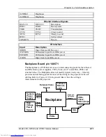
The IR receivers are not located on the SCB but are directly controlled by the
CPU and are connected via the backplane.
IIC Interface
The IIC Interface is used to transfer operating data to the circuit boards. IIC is a
protocol for a chipset made by Phillips. It is a bi-directional serial
communications interface. The IIC uses three (3) lines for communications: a
clock line (IICCLK), a data line (IICDATA), and an interrupt line (/IICINT). The
SCB is the master when communicating over the IIC with the other circuit boards
being slaves. The SCB sends information to another board by sending an address
then data. When the circuit boards have information to communicate to the SCB,
an interrupt is generated.
The SCB polls the boards to see who sent the interrupt. The SCB then reads the
information from the IIC bus.
One primary use of the IIC in the projector, in addition to its use as a data transfer
device, is control of the differential serial communications bus.
Serial Interface
The Serial Interface is a differential communication bus used for transferring data
quickly from the SCB to the other boards. It is unidirectional. In order for any
board to receive a packet of data via the Serial Interface, it must first be
commanded to receive that data by the IIC interface. Then the data is sent over the
differential bus to the receiving board. Once a packet of data has been sent, the IIC
must again be used to allow another packet to be received.
General I/O
This section describes the inputs to and outputs from the SCB. The I/O
descriptions are arranged by the source/destination of the signal. The assemblies
communicated with are the primary heading of each group of signals and are
further subdivided into inputs and outputs. In each case, the signal's direction is
noted, with input referring to an input to the SCB, and output to an output from
the SCB. (e.g. under Raster Timing Generator; 'Input'; /MAPST refers to the
signal /MAPST that is an input to the SCB from the Raster Timing Generator
Board). Any test points provided are noted.


