background image

31

AV COMPU LINK Remote Control System

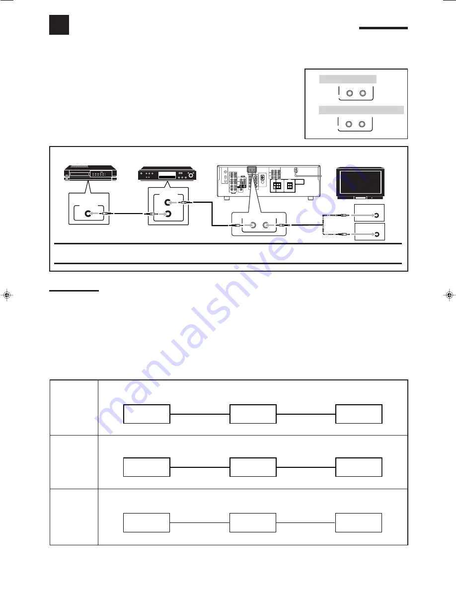
The AV COMPU LINK remote control system allows you to operate JVC’s video components (TV, VCR, and DVD player)
through the receiver.

RX-5040B/RX-5042S/RX-5045B are equipped with conventional AV COMPU LINK, while
RX-6040B/RX-6042S are equipped with the AV COMPU LINK-III, which adds a function to
operate JVC’s video components through the component video jacks.

To use this remote control system, connect the video components you want to operate,
following the diagrams below and the procedure on the next page.

CONNECTIONS 1: AV COMPU LINK Connection

CAUTION:

You can only connect to the TV with the AV COMPU LINK EX or AV COMPU LINK-III jack.
DO NOT connect to the TV with AV COMPU LINK RECEIVER/AMP jack.

Notes:

• For RX-6040B/RX-6042S: When connecting the receiver and a TV with the AV COMPU LINK EX jack by using a component video cable, you

cannot use automatic selection of TV’s input mode (see page 32).

• Make sure that the remote control code for the connected VCR is set to code “A.”
• When connecting only the VCR or DVD player to the receiver, connect it directly to the receiver using cables with the monaural mini-plugs.

CONNECTIONS 2: Video Cable Connection

Connect the VCR and/or DVD player to the TV using one of the following methods:

For RX-6040B/RX-6042S: When using the AV COMPU LINK remote control system, set the component video input for the DVD
player and the VCR correctly

 (see “Setting the Component Video Input” on page 22); otherwise, the correct input for this receiver will

not be selected on the TV.

When connecting the source equipment to the receiver through the 

S-video jacks

, connect the receiver

to the TV’s 

video input 1

 jack (S-video input) using S-video cables.

When connecting the source equipment to the receiver through the 

composite video jacks

, connect

the receiver to the TV’s 

video input 2

 jack (composite video input) using composite video cables.

When connecting the source equipment to the receiver through the 

component video jacks

, connect

the receiver to the TV’s 

video input 2

 jack (component video input) using component video cables.

Source

equipment

This receiver

TV

To video input 1

S-video cable

S-video cable

Source

equipment

TV

To video input 2

Composite

video cable

Composite

video cable

Source

equipment

TV

To video input 2

Component

video cable

Component

video cable

VCR

DVD player

TV

This receiver

This receiver

(Only for
RX-6040B/
RX-6042S)

CASE 2

CASE 1

CASE 3

AV

COMPU LINK 

AV

COMPU LINK – III

RX-5040B/RX-5042S/RX-5045B

RX-6040B/RX-6042S

AV

COMPU LINK

VHS

AV

COMPU LINK

AV

COMPU LINK EX

DVD

AV

COMPU LINK-

ΙΙΙ

This receiver

(Only for
RX-6040B/
RX-6042S)

31-39_5040&6040[J]f.p65

03.12.19, 2:38

31

Summary of Contents for 0404RYMMDWJEIN

Page 1: ...45B AUDIO VIDEO CONTROL RECEIVER INSTRUCTIONS For Customer Use Enter below the Model No and Serial No which are located either on the rear bottom or side of the cabinet Retain this information for future reference Model No Serial No TA NEWS INFO DISPLAY MODE ...

Page 2: ...RVICEABLE PARTS INSIDE REFER SERVICING TO QUALIFIED SERVICE PERSONNEL RISK OF ELECTRIC SHOCK DO NOT OPEN The lightning flash with arrowhead symbol within an equilateral triangle is intended to alert the user to the presence of uninsulated dangerous voltage within the product s enclosure that may be of sufficient magnitude to constitute a risk of electric shock to persons The exclamation point with...

Page 3: ...Components 7 7 Analog Connections 7 7 Digital Connections 10 Connecting the Power Cord 10 Basic Operations 11 Daily Operational Procedure 11 Turning On the Power 11 Selecting the Source to Play 11 Adjusting the Volume 12 Turning On and Off the Subwoofer Sound 13 Selecting the Analog or Digital Input Mode 13 Changing the Display Brightness 14 Attenuating the Input Signal 14 Changing the Source Name...

Page 4: ...ntheses for details 1 STANDBY ON button and STANDBY lamp 11 2 SURROUND DSP OFF button 27 29 3 DSP button 28 29 4 SURROUND button 27 5 Remote sensor 6 Display For details see Display on the next page 7 INPUT ANALOG button 14 INPUT ATT button 14 8 INPUT DIGITAL button 13 9 DIMMER button 14 p MASTER VOLUME control 12 q PHONES jack 13 w SPEAKERS ON OFF button 13 e SUBWOOFER OUT ON OFF button 13 r FM A...

Page 5: ...y turns on See pages in parentheses for details 1 ANALOG indicator 14 2 DUAL MONO indicator 26 27 3 H PHONE indicator 13 26 28 4 3D PHONIC indicator 26 28 5 VIRTUAL SB indicator 22 6 PRO LOGIC II indicator 25 27 28 7 DSP indicator 28 29 8 DIGITAL EQ indicator 24 9 Only for RX 6040B RX 6042S BASS BOOST indicator 15 0 TUNED indicator 16 STEREO indicator 16 INPUT ATT indicator 14 AUTO MUTING indicato...

Page 6: ...TER SPEAKER terminals 6 9 SURROUND SPEAKERS terminals 6 p FRONT SPEAKERS terminals 6 q AC power cord 10 Parts Identification CAUTION SPEAKER IMPEDANCE AM LOOP AM EXT CD IN OUT REC IN PLAY OUT REC VCR TV SOUND IN AV COMPU LINK III COMPU LINK 4 SYNCHRO ANTENNA CENTER SPEAKER SURROUND SPEAKERS RIGHT LEFT FRONT SPEAKERS RIGHT LEFT AUDIO RIGHT LEFT IN PLAY TAPE CDR DIGITAL 1 DIGITAL 2 CD DIGITAL IN DVD...

Page 7: ...g is missing contact your dealer immediately Putting Batteries in the Remote Control Before using the remote control insert the two supplied batteries first 1 Press and slide the battery cover on the back of the remote control 2 Insert the batteries Make sure to match the polarity to and to 3 Replace the cover If the remote control cannot transmit signals or operate the receiver correctly replace ...

Page 8: ...utdoor single vinyl covered wire not supplied to the AM EXT terminal Keep the AM loop antenna connected Connecting the Speakers and Subwoofer You can connect five speakers a pair of front speakers a center speaker and a pair of surround speakers and a subwoofer CAUTIONS Use only the speakers of the SPEAKER IMPEDANCE indicated by the speaker terminals Do not connect more than one speaker to each sp...

Page 9: ...to the TAPE CDR jacks change the source name to CDR which will be shown on the display when it is selected as the source See page 14 for details Connecting the subwoofer You can enhance the bass by connecting a subwoofer Connect the input jack of a powered subwoofer to the rear panel using a cable with RCA pin plugs not supplied Placing speakers Front speakers L R and center speaker C Place these ...

Page 10: ... video Composite video However the video signals from one type of these input jacks are transmitted only through the video output jacks of the same type If your video components have an AV COMPU LINK jack See also page 31 for detailed information about the connection and the AV COMPU LINK remote control system VCR Å To S video output ı To composite video output Ç To composite video input Î To S vi...

Page 11: ... correctly for AV COMPU LINK See page 22 for details Only for RX 6040B RX 6042S DVD player When you connect a DVD player with stereo output jacks Å To component video output ı To S video output Ç To composite video output Î To left right front channel audio output or to audio mixed output if necessary Notes For RX 6040B RX 6042S When connecting a DVD player to the component video input jacks make ...

Page 12: ... When you want to operate a DVD player or TV using the AV COMPU LINK remote control system see page 31 connect it also as described in Analog Connections see pages 8 and 9 Connecting the Power Cord Before plugging the receiver into an AC outlet make sure that all connections have been made Plug the power cord into an AC outlet Keep the power cord away from the connecting cables and the antenna The...

Page 13: ...X 5045B Note When connecting a CD recorder to the TAPE CDR jacks change the source name shown on the display For details see page 14 Daily Operational Procedure 1 Turn on the power See Turning On the Power below 2 Select the source See Selecting the Source to Play to the right 3 Adjust the volume See Adjusting the Volume on page 12 4 Select the Surround or DSP modes See Activating the Surround Mod...

Page 14: ... the source L C R LFE LS and RS light up Ex No sound comes out of the center speaker and surround speakers though center channel and surround channel signals are coming into this receiver How to understand the speaker and signal indicator illumination SB SB Selecting different sources for picture and sound While watching pictures from a video source you can listen to sound of an audio source Once ...

Page 15: ... the subwoofer output when you set SMALL for the front speakers on the speaker size setting see page 20 or using Quick Speaker Setup see page 18 You cannot activate the subwoofer output when you have set SUBWOOFER to SUBWOOFER NO see page 20 When you change the SUBWOOFER setting from SUBWOOFER NO to SUBWOOFER YES see page 20 subwoofer output is automatically activated Selecting the Analog or Digit...

Page 16: ... inconvenience TAPE will appear on the display when you select the CD recorder You cannot use the digital input see page 13 for the CD recorder When playing software encoded with Dolby Digital or DTS the following symptoms may occur Sound does not come out at the beginning of playback Noise comes out while searching for or skipping chapters or tracks In this case press INPUT DIGITAL repeatedly to ...

Page 17: ...memory This receiver memorizes sound settings for each source when you turn off the power when you change the source when you change the analog digital input modes and when you assign the source name see page 14 When you change the source the memorized settings for the newly selected source are automatically recalled The following can be stored for each source Analog digital input mode see page 13...

Page 18: ... station is tuned in Remote NOT Using Preset Tuning Once a station is assigned to a channel number the station can be quickly tuned in You can preset up to 30 FM and 15 AM stations To store the preset stations Before you start remember There is a time limit in doing the following steps If the setting is canceled before you finish start from step 2 again 1 Tune in the station you want to preset see...

Page 19: ...o broadcast is hard to receive or noisy you can change the FM reception mode while receiving an FM broadcast You can store the FM reception mode for each preset station see page 16 While listening to an FM station press FM MODE Each time you press the button the FM reception mode alternates between AUTO MUTING and MODE MONO AUTO MUTING Normally select this When a program is broadcasted in stereo y...

Page 20: ...PUSH SET COMPLETE appears on the display then goes back to the source indication Notes This procedure will not be completed if you stop in the middle of the setting process Once Quick Speaker Setup is performed the speaker output levels are also set to appropriate values automatically common to all sources If you want to set the speaker output levels separately for each source see Adjusting the Sp...

Page 21: ...e the bass LFE sounds 21 MIDNIGHT MODE Reproduce a powerful sound at night 21 DUAL MONO Select the Dual Mono sound channel 21 AUTO SURROUND Turn on or off Auto Surround 21 VIRTUAL SBACK Turn on or off Virtual Surround Back 22 DIGITAL IN Select the component connected to digital input terminal 22 VIDEO IN DVD 2 Select the type of video terminal used for the DVD player 22 VIDEO IN VCR 2 Select the t...

Page 22: ... Quick Speaker Setup on page 18 this setting is not required Subwoofer setting SUBWOOFER Select whether you have connected a subwoofer or not SUBWOOFER YES Select when a subwoofer is connected SUBWOOFER NO Select when no subwoofer is used Note If you have selected SUBWOOFER NO for the subwoofer you cannot use the SUBWOOFER OUT ON OFF button on the front panel Speaker size FRNT SPEAKERS CNTR SPEAKE...

Page 23: ...LTI Selecting the Main or Sub Channel You can select the playback sound channel you want while playing digital software recorded or broadcast in Dual Mono mode see page 26 which includes two monaural channels separately Dual Mono DUAL MONO Select the playback sounds channel MONO MAIN Select to play back the main channel Ch 1 Signal indicator L lights up while playing back this channel MONO SUB Sel...

Page 24: ...P modes see page 28 or one of the fixed digital input mode DOLBY DIGITAL or DTS SURROUND see page 14 and While listening with the headphones HEADPHONE or 3D H PHONE see pages 13 and 26 If you select another Surround mode or DSP mode or deactivate the Surround DSP mode manually Auto Surround if in use will be canceled temporarily for the currently selected source Auto Surround setting will be resto...

Page 25: ...On the following pages you can adjust the following items You can adjust only the items applicable to the current sound mode Items To do See page DEQ 63HZ Adjust equalizer pattern at 63 Hz 24 DEQ250HZ Adjust equalizer pattern at 250 Hz 24 DEQ 1KHZ Adjust equalizer pattern at 1 kHz 24 DEQ 4KHZ Adjust equalizer pattern at 4 kHz 24 DEQ16KHZ Adjust equalizer pattern at 16 kHz 24 SUBWFR LEVEL Adjust th...

Page 26: ...B to 8 dB in 2 dB steps When adjustment is made the DIGITAL EQ indicator lights up on the display To flat the equalization pattern set all the frequencies to 0 0 dB in step 4 of Basic Procedure on page 23 The DIGITAL EQ indicator goes off from the display Note The equalization patterns affect the front speaker sounds only Adjusting the Speaker Output Levels You can adjust the speaker output levels...

Page 27: ...han Dolby Pro Logic Another digital surround encoding format introduced by Dolby Laboratories is Dolby Digital EX which adds the third surround channels called surround back Compared to the conventional Dolby Digital 5 1CH these newly added surround back channels can reproduce more detailed movements behind you while viewing the video software In addition surround sound localization will become mo...

Page 28: ...r lights up You can enjoy its 5 1 channel sound with full quality What is Linear PCM Uncompressed digital audio data used for DVDs CDs and Video CDs DVDs support 2 channels with sampling rates of 48 96 kHz at quantization of 16 20 24 bits On the other hand CDs and Video CDs are limited to 2 channels with 44 1 kHz at 16 bits When Linear PCM signal is detected the indicator lights up What is Dual Mo...

Page 29: ... the memorized settings and adjustments see pages 18 to 24 Activating the Surround Modes Automatically You can enjoy the Surround mode simply by selecting the source with digital input selected for that source Auto Surround also works when the input mode changes from analog to digital To activate Auto Surround see page 21 Activating the Surround Modes Manually 1 Select and play any source excludin...

Page 30: ...p To use DSP modes press DSP so that the DSP modes change as follows The DSP indicator also lights up on the display HALL 1 HALL 2 LIVE CLUB DANCE CLUB PAVILION ALL CH STEREO THEATER 1 THEATER 2 MONO FILM Back to the beginning Digital Acoustic Processor DAP modes You can use the following DAP modes in order to reproduce a more acoustic sound field in your listening room HALL 1 Reproduces the spati...

Page 31: ... used The 3D PHONIC indicator lights up on the display If incoming signals change from 2 channel digital signal to another digital signal type MONO FILM is canceled and an appropriate Surround mode is activated Activating the DSP Modes Activating one of the DSP modes for a source automatically recalls the memorized settings and adjustments see pages 18 to 24 1 Select and play any source excluding ...

Page 32: ...starts recording When the play ends the cassette deck enters recording pause and stops about 4 seconds later Notes During synchronized recording the selected source cannot be changed If the power of any component is shut off during synchronized recording the COMPU LINK remote control system may not operate properly In this case you must start again from the beginning To use this remote control sys...

Page 33: ...d or DVD player to the TV using one of the following methods For RX 6040B RX 6042S When using the AV COMPU LINK remote control system set the component video input for the DVD player and the VCR correctly see Setting the Component Video Input on page 22 otherwise the correct input for this receiver will not be selected on the TV When connecting the source equipment to the receiver through the S vi...

Page 34: ...TV with the AV COMPU LINK EX jack using a component video cable In this case reconnect the TV referring to CASE 1 or CASE 2 on page 31 Automatic Power On Off Standby The TV VCR and DVD player turn on and off along with the receiver When you turn on the receiver If the previously selected source is the VCR the TV and VCR will turn on automatically If the previously selected source is the DVD player...

Page 35: ... To operate JVC s audio components using the supplied remote control You need to connect JVC s audio components through the COMPU LINK SYNCHRO jacks see page 30 in addition to the connections using cables with RCA pin plugs see page 7 Aim the remote control directly at the remote sensor on the receiver If you use the buttons on the front panel to choose a source the remote control will not operate...

Page 36: ...ect a track number always enter two digits 3 Press 3 to start playback Examples Selecting disc number 3 track number 2 and starting playback Press 3 then 0 2 then 3 Selecting disc number 10 track number 5 and starting playback Press 1 0 then 0 5 then 3 Selecting disc number 105 track number 12 and starting playback Press 1 0 5 then 1 2 then 3 Note It is required to press each button within 4 secon...

Page 37: ...t change the channels of some TVs by pressing the 10 keys press TV CATV CH for changing the channels 6 Try to operate your TV by pressing STANDBY ON TV CATV When your TV turns on or off you have entered the correct code If there are more than one code listed for your brand of TV try each one until the correct one is entered To change the transmittable signals for operating a CATV converter 1 Set t...

Page 38: ... you have entered the correct code To change the transmittable signals for operating another manufacturer s VCR 1 Press and hold STANDBY ON VCR 2 Press VCR 3 Enter a manufacturer s code using buttons 1 9 and 0 Manufacturer Codes JVC 01 02 03 Emerson 10 22 Gold Star 11 Hitachi 04 Mitsubishi 12 NEC 21 Panasonic 07 13 Philips 09 RCA 05 06 Samsung 20 Sanyo 17 18 19 Sony 14 15 16 Zenith 08 01 is the in...

Page 39: ...power cord contact your dealer Remove the obstruction Replace batteries See page 5 Select the correct remote control operation mode See pages 33 to 36 This is normal for DVD MULTI POSSIBLE CAUSE The power cord is not plugged in Speaker signal cables are not connected The SPEAKERS ON OFF button is not set correctly An incorrect source is selected Muting is activated An incorrect input mode analog o...

Page 40: ...Corresponding to Linear PCM Dolby Digital and DTS Digital Surround with sampling frequency 32 kHz 44 1 kHz 48 kHz Recording Output Level TAPE CDR VCR 220 mV Signal to Noise Ratio 66 IHF 78 IHF CD TAPE CDR VCR TV SOUND DVD 87 dB 74 dB Frequency Response 8 Ω CD TAPE CDR VCR TV SOUND DVD 20 Hz to 50 kHz 1 dB 3 dB Bass Boost Only for RX 6040B RX 6042S 3 dB 1 dB at 100 Hz Equalization 5 bands 63 Hz 250...

Page 41: ... 5040B RX 5042S RX 5045B 435 mm x 146 5 mm x 369 5 mm 17 3 16 in x 5 13 16 in x 14 5 8 in Mass For RX 6040B RX 6042S 8 8 kg 19 5 lbs For RX 5040B RX 5042S RX 5045B 7 5 kg 16 6 lbs Designs and specifications are subject to change without notice Main differences between the models Models Output Input terminals Sources Functions COMPONENT S VIDEO Analog discrete DVD MULTI Bass Boost Center Tone AV Co...

Page 42: ...cleaning 4 Damage that occurs in shipment due to act of God and cosmetic damage 5 Signal reception problems and failures due to line power surge 6 Video Pick up Tubes CCD Image Sensor Cartridge Stylus Needle are covered for 90 days from the date of purchase 7 Batteries except that Rechargeable Batteries are covered for 90 days from the date of purchase There are no express warranties except as lis...

Page 43: ...rized servicer or visit our website at www JVC com Remember to retain your Bill of Sale for Warranty Service Do not service the television yourself Caution To prevent electrical shock do not open the cabinet There are no user serviceable parts inside Please refer to qualified service personnel for repairs Accessories To purchase accessories for your JVC product please call toll free 1 800 882 2345...

Page 44: ...VICTOR COMPANY OF JAPAN LIMITED 0104RYMMDWJEIN EN 2004 VICTOR COMPANY OF JAPAN LIMITED AUDIO VIDEO CONTROL RECEIVER RX 6040B RX 6042S RX 5040B RX 5042S RX 5045B ...

Page 45: ...LVT1140 002A C RX 6040B RX 6042S RX 5040B RX 5042S RX 5045B INSTRUCTIONS TA NEWS INFO DISPLAY MODE AUDIO VIDEO CONTROL RECEIVER RECEPTEUR DE COMMANDE AUDIO VIDEO English Français MANUEL D INSTRUCTIONS ...

Page 46: ...RVICEABLE PARTS INSIDE REFER SERVICING TO QUALIFIED SERVICE PERSONNEL RISK OF ELECTRIC SHOCK DO NOT OPEN The lightning flash with arrowhead symbol within an equilateral triangle is intended to alert the user to the presence of uninsulated dangerous voltage within the product s enclosure that may be of sufficient magnitude to constitute a risk of electric shock to persons The exclamation point with...

Page 47: ...deo Components 7 7 Analog Connections 7 7 Digital Connections 10 Connecting the Power Cord 10 Basic Operations 11 Daily Operational Procedure 11 Turning On the Power 11 Selecting the Source to Play 11 Adjusting the Volume 12 Turning On and Off the Subwoofer Sound 13 Selecting the Analog or Digital Input Mode 13 Changing the Display Brightness 14 Attenuating the Input Signal 14 Changing the Source ...

Page 48: ...parentheses for details 1 STANDBY ON button and STANDBY lamp 11 2 SURROUND DSP OFF button 27 29 3 DSP button 28 29 4 SURROUND button 27 5 Remote sensor 6 Display For details see Display on the next page 7 INPUT ANALOG button 14 INPUT ATT button 14 8 INPUT DIGITAL button 13 9 DIMMER button 14 p MASTER VOLUME control 12 q PHONES jack 13 w SPEAKERS ON OFF button 13 e SUBWOOFER OUT ON OFF button 13 r ...

Page 49: ...cally turns on See pages in parentheses for details 1 ANALOG indicator 14 2 DUAL MONO indicator 26 27 3 H PHONE indicator 13 26 28 4 3D PHONIC indicator 26 28 5 VIRTUAL SB indicator 22 6 PRO LOGIC II indicator 25 27 28 7 DSP indicator 28 29 8 DIGITAL EQ indicator 24 9 Only for RX 6040B RX 6042S BASS BOOST indicator 15 0 TUNED indicator 16 STEREO indicator 16 INPUT ATT indicator 14 AUTO MUTING indi...

Page 50: ... CENTER SPEAKER terminals 6 9 SURROUND SPEAKERS terminals 6 p FRONT SPEAKERS terminals 6 q AC power cord 10 Parts Identification CAUTION SPEAKER IMPEDANCE AM LOOP AM EXT CD IN OUT REC IN PLAY OUT REC VCR TV SOUND IN AV COMPU LINK III COMPU LINK 4 SYNCHRO ANTENNA CENTER SPEAKER SURROUND SPEAKERS RIGHT LEFT FRONT SPEAKERS RIGHT LEFT AUDIO RIGHT LEFT IN PLAY TAPE CDR DIGITAL 1 DIGITAL 2 CD DIGITAL IN...

Page 51: ...s missing contact your dealer immediately Putting Batteries in the Remote Control Before using the remote control insert the two supplied batteries first 1 Press and slide the battery cover on the back of the remote control 2 Insert the batteries Make sure to match the polarity to and to 3 Replace the cover If the remote control cannot transmit signals or operate the receiver correctly replace the...

Page 52: ...an outdoor single vinyl covered wire not supplied to the AM EXT terminal Keep the AM loop antenna connected Connecting the Speakers and Subwoofer You can connect five speakers a pair of front speakers a center speaker and a pair of surround speakers and a subwoofer CAUTIONS Use only the speakers of the SPEAKER IMPEDANCE indicated by the speaker terminals Do not connect more than one speaker to eac...

Page 53: ...der to the TAPE CDR jacks change the source name to CDR which will be shown on the display when it is selected as the source See page 14 for details Connecting the subwoofer You can enhance the bass by connecting a subwoofer Connect the input jack of a powered subwoofer to the rear panel using a cable with RCA pin plugs not supplied Placing speakers Front speakers L R and center speaker C Place th...

Page 54: ...eo S video Composite video However the video signals from one type of these input jacks are transmitted only through the video output jacks of the same type If your video components have an AV COMPU LINK jack See also page 31 for detailed information about the connection and the AV COMPU LINK remote control system VCR Å To S video output ı To composite video output Ç To composite video input Î To ...

Page 55: ... DVD correctly for AV COMPU LINK See page 22 for details Only for RX 6040B RX 6042S DVD player When you connect a DVD player with stereo output jacks Å To component video output ı To S video output Ç To composite video output Î To left right front channel audio output or to audio mixed output if necessary Notes For RX 6040B RX 6042S When connecting a DVD player to the component video input jacks m...

Page 56: ...ge 7 When you want to operate a DVD player or TV using the AV COMPU LINK remote control system see page 31 connect it also as described in Analog Connections see pages 8 and 9 Connecting the Power Cord Before plugging the receiver into an AC outlet make sure that all connections have been made Plug the power cord into an AC outlet Keep the power cord away from the connecting cables and the antenna...

Page 57: ...2S RX 5045B Note When connecting a CD recorder to the TAPE CDR jacks change the source name shown on the display For details see page 14 Daily Operational Procedure 1 Turn on the power See Turning On the Power below 2 Select the source See Selecting the Source to Play to the right 3 Adjust the volume See Adjusting the Volume on page 12 4 Select the Surround or DSP modes See Activating the Surround...

Page 58: ...d as the source L C R LFE LS and RS light up Ex No sound comes out of the center speaker and surround speakers though center channel and surround channel signals are coming into this receiver How to understand the speaker and signal indicator illumination SB SB Selecting different sources for picture and sound While watching pictures from a video source you can listen to sound of an audio source O...

Page 59: ...activate the subwoofer output when you set SMALL for the front speakers on the speaker size setting see page 20 or using Quick Speaker Setup see page 18 You cannot activate the subwoofer output when you have set SUBWOOFER to SUBWOOFER NO see page 20 When you change the SUBWOOFER setting from SUBWOOFER NO to SUBWOOFER YES see page 20 subwoofer output is automatically activated Selecting the Analog ...

Page 60: ...some inconvenience TAPE will appear on the display when you select the CD recorder You cannot use the digital input see page 13 for the CD recorder When playing software encoded with Dolby Digital or DTS the following symptoms may occur Sound does not come out at the beginning of playback Noise comes out while searching for or skipping chapters or tracks In this case press INPUT DIGITAL repeatedly...

Page 61: ...uto memory This receiver memorizes sound settings for each source when you turn off the power when you change the source when you change the analog digital input modes and when you assign the source name see page 14 When you change the source the memorized settings for the newly selected source are automatically recalled The following can be stored for each source Analog digital input mode see pag...

Page 62: ...il a station is tuned in Remote NOT Using Preset Tuning Once a station is assigned to a channel number the station can be quickly tuned in You can preset up to 30 FM and 15 AM stations To store the preset stations Before you start remember There is a time limit in doing the following steps If the setting is canceled before you finish start from step 2 again 1 Tune in the station you want to preset...

Page 63: ...tereo broadcast is hard to receive or noisy you can change the FM reception mode while receiving an FM broadcast You can store the FM reception mode for each preset station see page 16 While listening to an FM station press FM MODE Each time you press the button the FM reception mode alternates between AUTO MUTING and MODE MONO AUTO MUTING Normally select this When a program is broadcasted in ster...

Page 64: ...JOG PUSH SET COMPLETE appears on the display then goes back to the source indication Notes This procedure will not be completed if you stop in the middle of the setting process Once Quick Speaker Setup is performed the speaker output levels are also set to appropriate values automatically common to all sources If you want to set the speaker output levels separately for each source see Adjusting th...

Page 65: ...nuate the bass LFE sounds 21 MIDNIGHT MODE Reproduce a powerful sound at night 21 DUAL MONO Select the Dual Mono sound channel 21 AUTO SURROUND Turn on or off Auto Surround 21 VIRTUAL SBACK Turn on or off Virtual Surround Back 22 DIGITAL IN Select the component connected to digital input terminal 22 VIDEO IN DVD 2 Select the type of video terminal used for the DVD player 22 VIDEO IN VCR 2 Select t...

Page 66: ... Quick Speaker Setup on page 18 this setting is not required Subwoofer setting SUBWOOFER Select whether you have connected a subwoofer or not SUBWOOFER YES Select when a subwoofer is connected SUBWOOFER NO Select when no subwoofer is used Note If you have selected SUBWOOFER NO for the subwoofer you cannot use the SUBWOOFER OUT ON OFF button on the front panel Speaker size FRNT SPEAKERS CNTR SPEAKE...

Page 67: ...VD MULTI Selecting the Main or Sub Channel You can select the playback sound channel you want while playing digital software recorded or broadcast in Dual Mono mode see page 26 which includes two monaural channels separately Dual Mono DUAL MONO Select the playback sounds channel MONO MAIN Select to play back the main channel Ch 1 Signal indicator L lights up while playing back this channel MONO SU...

Page 68: ...e of the fixed digital input mode DOLBY DIGITAL or DTS SURROUND see page 14 and While listening with the headphones HEADPHONE or 3D H PHONE see pages 13 and 26 If you select another Surround mode or DSP mode or deactivate the Surround DSP mode manually Auto Surround if in use will be canceled temporarily for the currently selected source Auto Surround setting will be restored in the following case...

Page 69: ...ems On the following pages you can adjust the following items You can adjust only the items applicable to the current sound mode Items To do See page DEQ 63HZ Adjust equalizer pattern at 63 Hz 24 DEQ250HZ Adjust equalizer pattern at 250 Hz 24 DEQ 1KHZ Adjust equalizer pattern at 1 kHz 24 DEQ 4KHZ Adjust equalizer pattern at 4 kHz 24 DEQ16KHZ Adjust equalizer pattern at 16 kHz 24 SUBWFR LEVEL Adjus...

Page 70: ... 8 dB to 8 dB in 2 dB steps When adjustment is made the DIGITAL EQ indicator lights up on the display To flat the equalization pattern set all the frequencies to 0 0 dB in step 4 of Basic Procedure on page 23 The DIGITAL EQ indicator goes off from the display Note The equalization patterns affect the front speaker sounds only Adjusting the Speaker Output Levels You can adjust the speaker output le...

Page 71: ...re than Dolby Pro Logic Another digital surround encoding format introduced by Dolby Laboratories is Dolby Digital EX which adds the third surround channels called surround back Compared to the conventional Dolby Digital 5 1CH these newly added surround back channels can reproduce more detailed movements behind you while viewing the video software In addition surround sound localization will becom...

Page 72: ... signal is detected the indicator lights up You can enjoy its 5 1 channel sound with full quality What is Linear PCM Uncompressed digital audio data used for DVDs CDs and Video CDs DVDs support 2 channels with sampling rates of 48 96 kHz at quantization of 16 20 24 bits On the other hand CDs and Video CDs are limited to 2 channels with 44 1 kHz at 16 bits When Linear PCM signal is detected the ind...

Page 73: ...alls the memorized settings and adjustments see pages 18 to 24 Activating the Surround Modes Automatically You can enjoy the Surround mode simply by selecting the source with digital input selected for that source Auto Surround also works when the input mode changes from analog to digital To activate Auto Surround see page 21 Activating the Surround Modes Manually 1 Select and play any source excl...

Page 74: ...t the DSP modes change as follows The DSP indicator also lights up on the display HALL 1 HALL 2 LIVE CLUB DANCE CLUB PAVILION ALL CH STEREO THEATER 1 THEATER 2 MONO FILM Back to the beginning Digital Acoustic Processor DAP modes You can use the following DAP modes in order to reproduce a more acoustic sound field in your listening room HALL 1 Reproduces the spatial feeling of a large shoebox shape...

Page 75: ...y is used The 3D PHONIC indicator lights up on the display If incoming signals change from 2 channel digital signal to another digital signal type MONO FILM is canceled and an appropriate Surround mode is activated Activating the DSP Modes Activating one of the DSP modes for a source automatically recalls the memorized settings and adjustments see pages 18 to 24 1 Select and play any source exclud...

Page 76: ...eck starts recording When the play ends the cassette deck enters recording pause and stops about 4 seconds later Notes During synchronized recording the selected source cannot be changed If the power of any component is shut off during synchronized recording the COMPU LINK remote control system may not operate properly In this case you must start again from the beginning To use this remote control...

Page 77: ...R and or DVD player to the TV using one of the following methods For RX 6040B RX 6042S When using the AV COMPU LINK remote control system set the component video input for the DVD player and the VCR correctly see Setting the Component Video Input on page 22 otherwise the correct input for this receiver will not be selected on the TV When connecting the source equipment to the receiver through the ...

Page 78: ...the TV with the AV COMPU LINK EX jack using a component video cable In this case reconnect the TV referring to CASE 1 or CASE 2 on page 31 Automatic Power On Off Standby The TV VCR and DVD player turn on and off along with the receiver When you turn on the receiver If the previously selected source is the VCR the TV and VCR will turn on automatically If the previously selected source is the DVD pl...

Page 79: ...ORTANT To operate JVC s audio components using the supplied remote control You need to connect JVC s audio components through the COMPU LINK SYNCHRO jacks see page 30 in addition to the connections using cables with RCA pin plugs see page 7 Aim the remote control directly at the remote sensor on the receiver If you use the buttons on the front panel to choose a source the remote control will not o...

Page 80: ...sc number 2 Then select a track number always enter two digits 3 Press 3 to start playback Examples Selecting disc number 3 track number 2 and starting playback Press 3 then 0 2 then 3 Selecting disc number 10 track number 5 and starting playback Press 1 0 then 0 5 then 3 Selecting disc number 105 track number 12 and starting playback Press 1 0 5 then 1 2 then 3 Note It is required to press each b...

Page 81: ...annot change the channels of some TVs by pressing the 10 keys press TV CATV CH for changing the channels 6 Try to operate your TV by pressing STANDBY ON TV CATV When your TV turns on or off you have entered the correct code If there are more than one code listed for your brand of TV try each one until the correct one is entered To change the transmittable signals for operating a CATV converter 1 S...

Page 82: ... off you have entered the correct code To change the transmittable signals for operating another manufacturer s VCR 1 Press and hold STANDBY ON VCR 2 Press VCR 3 Enter a manufacturer s code using buttons 1 9 and 0 Manufacturer Codes JVC 01 02 03 Emerson 10 22 Gold Star 11 Hitachi 04 Mitsubishi 12 NEC 21 Panasonic 07 13 Philips 09 RCA 05 06 Samsung 20 Sanyo 17 18 19 Sony 14 15 16 Zenith 08 01 is th...

Page 83: ... AC power cord contact your dealer Remove the obstruction Replace batteries See page 5 Select the correct remote control operation mode See pages 33 to 36 This is normal for DVD MULTI POSSIBLE CAUSE The power cord is not plugged in Speaker signal cables are not connected The SPEAKERS ON OFF button is not set correctly An incorrect source is selected Muting is activated An incorrect input mode anal...

Page 84: ... nm Corresponding to Linear PCM Dolby Digital and DTS Digital Surround with sampling frequency 32 kHz 44 1 kHz 48 kHz Recording Output Level TAPE CDR VCR 220 mV Signal to Noise Ratio 66 IHF 78 IHF CD TAPE CDR VCR TV SOUND DVD 87 dB 74 dB Frequency Response 8 Ω CD TAPE CDR VCR TV SOUND DVD 20 Hz to 50 kHz 1 dB 3 dB Bass Boost Only for RX 6040B RX 6042S 3 dB 1 dB at 100 Hz Equalization 5 bands 63 Hz...

Page 85: ...09 5 mm For RX 5040B RX 5042S RX 5045B 435 mm x 146 5 mm x 369 5 mm Mass For RX 6040B RX 6042S 8 8 kg For RX 5040B RX 5042S RX 5045B 7 5 kg Designs and specifications are subject to change without notice Main differences between the models Models Output Input terminals Sources Functions COMPONENT S VIDEO Analog discrete DVD MULTI Bass Boost Center Tone AV Compulink IN OUT IN OUT DVD MULTI RX 6040B...

Page 86: ...VICTOR COMPANY OF JAPAN LIMITED 0104RYMMDWJEIN EN FR 2004 VICTOR COMPANY OF JAPAN LIMITED AUDIO VIDEO CONTROL RECEIVER RX 6040B RX 6042S RX 5040B RX 5042S RX 5045B ...

Reviews: