background image

4

English

AM

LOOP

AM

EXT

ANTENNA

COAXIAL

FM 75

FM  75  

COAXIAL

AM
LOOP

AM
EXT

ANTENNA

FM  75  

COAXIAL

AM
LOOP

AM
EXT

ANTENNA

Getting Started

This section explains how to connect audio/video components and speakers to the receiver, and how to connect the
power supply.

Before Installation

General Precautions

• Be sure your hands are dry.
• Turn the power off to all components.
• Read the manuals supplied with the components you are going to connect.

Locations

• Install the receiver in a location that is level and protected from

moisture and dust.

• The temperature around the receiver must be between –5˚C and 35˚C.
• Make sure there is good ventilation around the receiver. Poor

ventilation could cause overheating and damage the receiver.

Handling the receiver

• Do not insert any metal object into the receiver.
• Do not disassemble the receiver or remove screws, covers, or cabinet.
• Do not expose the receiver to rain or moisture.

Checking the Supplied Accessories

Check to be sure you have all of the following items, which are
supplied with the receiver.
The number in the parentheses indicates quantity of the pieces supplied.

• Remote Control (1)
• Batteries (2)
• AM Loop Antenna (1)
• FM Antenna (1)
• AC Plug Adaptor (1)

If anything is missing, contact your dealer immediately.

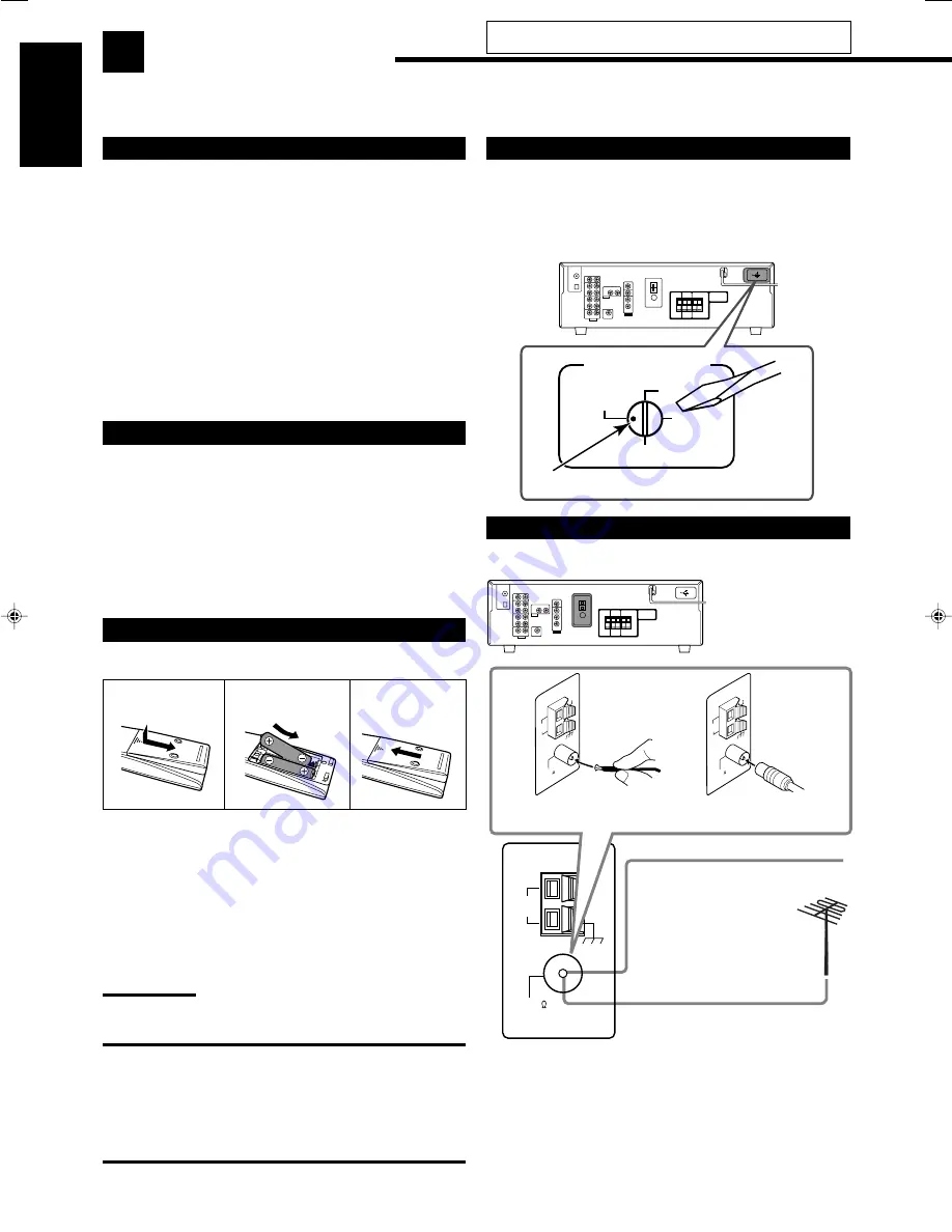
Putting Batteries in the Remote Control

Before using the remote control, insert the two supplied batteries first.

1 Press and slide the battery cover on the back of

the remote control.

2 Insert the batteries.

• Make sure to match the polarity: (+) to (+) and (–) to (–).

3 Replace the cover.

If the remote control cannot transmit signals or operate the receiver
correctly, replace the batteries. Use two R6(SUM-3)/AA(15F) type
dry-cell batteries.

Note:

Supplied batteries are for the initial setup. Replace for continued use.

CAUTION:

Follow these precautions to avoid leaking or cracking cells:
• Place batteries in the remote control so they match the

polarity: (+) to (+) and (–) to (–).

• Use the correct type of batteries. Batteries that look similar

may differ in voltage.

• Always replace both batteries at the same time.
• Do not expose batteries to heat or flame.

1

2

R6(SUM-3)/
AA(15F)

3

B

FM Antenna
(supplied)

Outdoor FM Antenna Cable
(not supplied)

Extend the supplied FM antenna
horizontally.

A

Do not connect the AC power cord until all other connections
have been made.

Adjusting the Voltage Selector

Before connections, always do the following first if necessary.
Select the correct voltage with the VOLTAGE SELECTOR switch
on the rear using a screw driver.
Check to be sure if the voltage mark is set to the voltage for the area
where you use this unit.

Connecting the FM and AM Antennas

FM antenna connections

Connect the supplied FM antenna as temporary measure to the
FM 75 

 COAXIAL terminal—

A

If reception is poor, connect the outdoor FM antenna (not
supplied)—

B

1

Disconnect the supplied FM antenna.

2

Connect a 75 

 coaxial cable with the standard type connector

(IEC or DIN45325).

VOLTAGE SELECTOR

220V

230


-


240V

127V

110V

Voltage mark

01-08_5052[US]2.p65

05.1.7, 5:03 PM

4

Summary of Contents for 0105RYMMDWJEIN

Page 1: ...LVT1290 007A US UN RX 5052S AUDIO VIDEO CONTROL RECEIVER TA NEWS INFO DISPLAY MODE INSTRUCTIONS English ...

Page 2: ...wed strictly Do not expose this apparatus to rain moisture dripping or splashing and that no objects filled with liquids such as vases shall be placed on the apparatus CAUTION To reduce the risk of electrical shocks fire etc 1 Do not remove screws covers or cabinet 2 Do not expose this appliance to rain or moisture Caution Proper Ventilation To avoid risk of electric shock and fire and to protect ...

Page 3: ...tions 6 7 Digital Connections 8 Connecting the Power Cord 8 Basic Operations 9 Daily Operational Procedure 9 Turning On the Power 9 Selecting the Source to Play 9 Adjusting the Volume 10 Turning On and Off the Subwoofer Sound 11 Selecting the Analog or Digital Input Mode 11 Changing the Display Brightness 12 Attenuating the Input Signal 12 Changing the Source Name 12 Muting the Sound 13 Using the ...

Page 4: ...RROUND button 25 5 Remote sensor 6 Display For details see Display below 7 Source selection buttons 9 12 DVD VCR TV SOUND CD TAPE CDR SOURCE NAME FM AM 8 INPUT ANALOG button 12 INPUT ATT button 12 9 INPUT DIGITAL button 11 p DIMMER button 12 q MASTER VOLUME control 10 w PHONES jack 11 e SPEAKERS ON OFF button 11 r SUBWOOFER OUT ON OFF button 11 t FM AM TUNING 5 buttons 14 y FM AM PRESET 5 buttons ...

Page 5: ... 12 28 SURROUND DSP OFF button 25 27 28 DSP button 26 28 MUTING button 13 28 VOLUME button 10 28 TV VOLUME buttons 29 Note When you press the one of the audio source selection buttons TAPE CDR CD and FM AM on the remote control the receiver automatically turns on Rear Panel CAUTION SPEAKER IMPEDANCE AM LOOP AM EXT CD IN OUT REC IN PLAY OUT REC VCR TV SOUND IN ANTENNA CENTER SPEAKER SURROUND SPEAKE...

Page 6: ...ide the battery cover on the back of the remote control 2 Insert the batteries Make sure to match the polarity to and to 3 Replace the cover If the remote control cannot transmit signals or operate the receiver correctly replace the batteries Use two R6 SUM 3 AA 15F type dry cell batteries Note Supplied batteries are for the initial setup Replace for continued use CAUTION Follow these precautions ...

Page 7: ... connected AM Loop Antenna supplied Outdoor single vinyl covered wire not supplied Snap the tabs on the loop into the slots of the base to assemble the AM loop antenna 1 2 3 Connecting the Speakers and Subwoofer You can connect five speakers a pair of front speakers a center speaker and a pair of surround speakers and a subwoofer CAUTIONS Use only the speakers of the SPEAKER IMPEDANCE indicated by...

Page 8: ...cted as the source See page 12 for details Connecting the subwoofer You can enhance the bass by connecting a subwoofer Connect the input jack of a powered subwoofer to the rear panel using a cable with RCA pin plugs not supplied Placing speakers Front speakers L R and center speaker C Place these speakers at the same height from the floor at or near ear level Array across the front of the viewing ...

Page 9: ...io output Ç To composite video input Î To composite video output TV Connect the TV to appropriate MONITOR OUT jacks to view the playback picture from any other connected video components DVD player Å To composite video output ı To left right front channel audio output or to audio mixed output if necessary Note To enjoy Dolby Digital and DTS multi channel software including Dual Mono software conne...

Page 10: ...adjustment may be erased in a few days in the following cases When you unplug the power cord When a power failure occurs If the wall outlet does not match the AC plug use the supplied AC plug adaptor CAUTIONS Do not plug in before setting the VOLTAGE SELECTOR switch on the rear of the unit and all connection procedures are complete Do not touch the power cord with wet hands Do not pull on the powe...

Page 11: ...tional Procedure 1 Turn on the power See Turning On the Power below 2 Select the source See Selecting the Source to Play to the right 3 Adjust the volume See Adjusting the Volume on page 10 4 Select the Surround or DSP modes See Activating the Surround Modes page 25 and Activating the DSP Modes page 27 Turning On the Power Press STANDBY ON or STANDBY ON AUDIO on the remote control The STANDBY lamp...

Page 12: ...in S Lights up when the monaural surround channel signal comes in SB Lights up when the surround back channel signal comes in Ex No sound comes out of the center speaker and surround speakers though center channel and surround channel signals are coming into this receiver How to understand the speaker and signal indicator illumination Selecting different sources for picture and sound While watchin...

Page 13: ...activate the subwoofer output when you set SMALL for the front speakers on the speaker size setting see page 18 or using Quick Speaker Setup see page 16 You cannot activate the subwoofer output when you have set SUBWOOFER to SUBWOOFER NO see page 18 When you change the SUBWOOFER setting from SUBWOOFER NO to SUBWOOFER YES see page 18 subwoofer output is automatically activated Selecting the Analog ...

Page 14: ...he display when you select the CD recorder You cannot use the digital input see page 11 for the CD recorder When playing software encoded with Dolby Digital or DTS the following symptoms may occur Sound does not come out at the beginning of playback Noise comes out while searching for or skipping chapters or tracks In this case press INPUT DIGITAL repeatedly to select DOLBY DIGITAL or DTS SURROUND...

Page 15: ...he receiver to a cassette deck or a CD recorder connected to the TAPE CDR jacks and the VCR connected to the VCR jacks at the same time While recording you can listen to the selected sound source at whatever sound level you like without affecting the sound levels of the recording Note The output volume level Midnight Mode see page 19 Equalization patterns see page 22 Surround modes and DSP modes s...

Page 16: ...on of sufficient signal strength is tuned in the TUNED indicator lights up on the display When an FM stereo program is received the STEREO indicator also lights up When you hold and then release the button in step 2 the frequency keeps changing until a station is tuned in Using Preset Tuning Once a station is assigned to a channel number the station can be quickly tuned in You can preset up to 30 ...

Page 17: ...eceive or noisy you can change the FM reception mode while receiving an FM broadcast You can store the FM reception mode for each preset station see page 14 While listening to an FM station press FM MODE Each time you press the button the FM reception mode alternates between AUTO MUTING and MODE MONO AUTO MUTING Normally select this When a program is broadcasted in stereo you will hear stereo soun...

Page 18: ...ce indication Note This procedure will not be completed if you stop in the middle of the setting process Speaker channel number and speaker size You can find how each of the speaker size is defined according to the number of connected speakers speaker channel CH number you select Subwoofer S WFR is counted as 0 1 channel The size of the connected speakers CH L R C LS RS S WFR 2 0CH LARGE NONE NONE...

Page 19: ...ubwoofer 18 CROSSOVER Select the cutoff frequency to the subwoofer 19 LFE ATTENUATE Attenuate the bass LFE sounds 19 MIDNIGHT MODE Reproduce a powerful sound at night 19 DUAL MONO Select the Dual Mono sound channel 19 AUTO SURROUND Turn on or off Auto Surround 20 VIRTUAL SBACK Turn on or off Virtual Surround Back 20 DIGITAL IN Select the component connected to digital input terminal 20 Note These ...

Page 20: ...p on page 16 this setting is not required Subwoofer setting SUBWOOFER Select whether you have connected a subwoofer or not SUBWOOFER YES Select when a subwoofer is connected SUBWOOFER NO Select when no subwoofer is used Note If you have selected SUBWOOFER NO for the subwoofer you cannot use the SUBWOOFER OUT ON OFF button on the front panel Speaker size FRNT SPEAKERS CNTR SPEAKER SURR SPEAKERS Sel...

Page 21: ...und at night using Midnight Mode Select one of the following MIDNIGHT 1 Select when you want to reduce the dynamic range a little MIDNIGHT 2 Select when you want to apply the compress effect fully useful at midnight MIDNIGHT OFF Select when you want to enjoy playback with its full dynamic range no effect applied Selecting the Main or Sub Channel You can select the playback sound channel you want w...

Page 22: ... 2TV 1DVD 2CDR 1CD 2DVD 1CD 2TV 1CD 2CDR 1TV 2DVD 1TV 2CD 1TV 2CDR 1CDR 2DVD 1CDR 2CD 1CDR 2TV back to the beginning Setting for Easy and Effective Surround Operations Auto Surround AUTO SURROUND Auto Surround works when the unit detects the incoming digital signal In other words it works When you select the digital source the source with digital input selected for it and When you change the input...

Page 23: ...ation resumes on the display Basic Adjustment Items On the following pages you can adjust the following items You can adjust only the items applicable to the current sound mode Items To do See page DEQ 63HZ Adjust equalizer pattern at 63 Hz 22 DEQ250HZ Adjust equalizer pattern at 250 Hz 22 DEQ 1KHZ Adjust equalizer pattern at 1 kHz 22 DEQ 4KHZ Adjust equalizer pattern at 4 kHz 22 DEQ16KHZ Adjust e...

Page 24: ...s You can adjust the equalization patterns to your preference Once you have made adjustment it is memorized for each source Equalization adjustment DEQ 63HZ DEQ250HZ DEQ 1KHZ DEQ 4KHZ DEQ16KHZ You can adjust five frequencies 63 Hz 250 Hz 1 kHz 4 kHz 16 kHz within the range of 8 dB to 8 dB in 2 dB steps When adjustment is made the DIGITAL EQ indicator lights up on the display To flat the equalizati...

Page 25: ...an Dolby Pro Logic Another digital surround encoding format introduced by Dolby Laboratories is Dolby Digital EX which adds the third surround channels called surround back Compared to the conventional Dolby Digital 5 1CH these newly added surround back channels can reproduce more detailed movements behind you while viewing the video software In addition surround sound localization will become mor...

Page 26: ... signal is detected the indicator lights up You can enjoy its 5 1 channel sound with full quality What is Linear PCM Uncompressed digital audio data used for DVDs CDs and Video CDs DVDs support 2 channels with sampling rates of 48 96 kHz at quantization of 16 20 24 bits On the other hand CDs and Video CDs are limited to 2 channels with 44 1 kHz at 16 bits When Linear PCM signal is detected the ind...

Page 27: ... source automatically recalls the memorized settings and adjustments see pages 16 to 22 Activating the Surround Modes Automatically You can enjoy the Surround mode simply by selecting the source with digital input selected for that source Auto Surround also works when the input mode changes from analog to digital To activate Auto Surround see page 20 Activating the Surround Modes Manually 1 Select...

Page 28: ...s change as follows The DSP indicator also lights up on the display HALL 1 HALL 2 LIVE CLUB DANCE CLUB PAVILION ALL CH STEREO THEATER 1 THEATER 2 MONO FILM Back to the beginning Digital Acoustic Processor DAP modes You can use the following DAP modes in order to reproduce a more acoustic sound field in your listening room HALL 1 Reproduces the spatial feeling of a large shoebox shaped hall designe...

Page 29: ...he front speakers only is used The 3D PHONIC indicator lights up on the display If incoming signals change from 2 channel digital signal to another digital signal type MONO FILM is canceled and an appropriate Surround mode is activated Activating the DSP Modes Activating one of the DSP modes for a source automatically recalls the memorized settings and adjustments see pages 16 to 22 1 Select and p...

Page 30: ...ALOG DIGITAL Switch the analog and digital input alternately DIMMER Dim or brighten the display SLEEP Set the Sleep Timer SURROUND Turn on and select Surround modes DSP Turn on and select DSP modes SURROUND DSP OFF Turn off the Surround and DSP mode After pressing SOUND you can perform the following operations by using the 10 keys FRONT L then LEVEL Adjust the left front speaker output level FRONT...

Page 31: ...TV 1 9 0 100 10 Select the channels RETURN 10 Alternate between the previously selected channel and the current channel MENU ENTER 4 7 P 10 2 8 6 CD changer After pressing CD DISC you can perform the following operations on a CD changer 3 Start playing 4 Return to the beginning of the current or previous track Skip to the beginning of the next track 7 Stop playing 8 Pause playing To resume press 3...

Page 32: ... the front panel to turn off the receiver After unplugging the AC power cord contact your dealer Remove the obstruction Replace batteries See page 4 Select the correct remote control operation mode See pages 28 and 29 POSSIBLE CAUSE The power cord is not plugged in Speaker signal cables are not connected The SPEAKERS ON OFF button is not set correctly An incorrect source is selected Muting is acti...

Page 33: ... and 240 V Audio Audio Input Sensitivity Impedance 1 kHz CD TAPE CDR VCR TV SOUND DVD 220 mV 47 kΩ Audio Input DIGITAL IN 2 Coaxial DIGITAL 1 DVD 0 5 V p p 75 Ω Optical DIGITAL 2 CD 21 dBm to 15 dBm 660 nm 30 nm 2 Corresponding to Linear PCM Dolby Digital and DTS Digital Surround with sampling frequency 32 kHz 44 1 kHz 48 kHz Recording Output Level TAPE CDR VCR 220 mV Signal to Noise Ratio 66 IHF ...

Page 34: ...35 dB at 1 kHz AM tuner Tuning Range 531 kHz to 1 602 kHz at 9 kHz intervals 530 kHz to 1 600 kHz at 10 kHz intervals General Power Requirements AC 110 V 127 V 220 V 230 V 240 V adjustable with the voltage selector 50 Hz 60 Hz Power Consumption 210 W at operation 4 5 W in standby mode Dimensions W x H x D 435 mm x 146 5 mm x 369 5 mm Mass 8 0 kg Designs and specifications are subject to change wit...

Page 35: ...mains AC line BEFORE PLUGGING IN do check that your mains AC line voltage corresponds with the position of the voltage selector switch provided on the outside of this equipment and if different reset the voltage selector switch to prevent from a damage or risk of fire electric shock 0105RYMMDWJEIN EN CS 2005 Victor Company of Japan Limited AUDIO VIDEO CONTROL RECEIVER RX 5052S ...

Reviews: