background image


JA95-001 Audio Controller 


Operating Manual


Page 6 


Note

:  Numbers in parentheses refer to the front panel 

controls shown in section 3.2. 


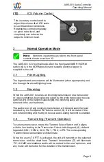
(12)


ICS Volume Control 


3  

Normal Operation Mode  


The JA95-001 is in Normal mode when the front panel EMER / NORM 
switch (

4

) is in the NORM position and suitable electrical power is 

supplied to the unit.


3.1  

Panel Lighting 

The legends and annunciators will be illuminated (when appropriate) and 
dim through the aircraft lighting buss. 

3.2  

Receiving  

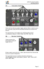
When the JA95-001 receives an incoming transmission on a transceiver 
or receiver that has been selected, either by the white transceiver receive 
switches 

(1) 

or the transmit selector 

(8)

, the incoming audio will be 

directed to the user’s phones.  

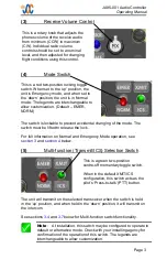
The audio level of any incoming transmission will depend upon the level 
selected by the front panel RX volume control (

3

). It will be muted if the 

unit is transmitting and muting of receive audio during transmit is enabled. 

3.3  

Transmitting (Transmit Operation) 

To select a transceiver, rotate the Transmit Select Switch until it aligns 
with the line leading to the Transceiver Select switch legend 

(1)

 - default 

legends COM 1, COM 2, AUX, FM 1, FM 2, or PA. The corresponding 
Transmit Select annunciator will illuminate. 

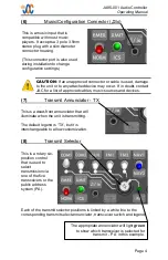
When the user’s TX PTT is activated, the unit will transmit on the selected 
transceiver, and the dead front Transmit Annunciator 

(7)

  will illuminate 

‘TX’. All MIC and sidetone audio will be routed to the user’s phones, and 
any music will be muted for the duration of the transmission.  

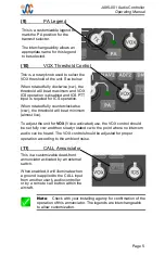
This is a rotary control used to 
adjust the volume of all ICS audio 
to suit the ambient conditions. 
Rotating the control completely 
cw gives rated level, and 
completely ccw reduces the 
output to minimum level. 


Summary of Contents for JA95-001

Page 1: ...figurable settings Field replaceable legends Stuck microphone time out Adjustable output and input levels Balanced ICS CVR Rx Comp transmit mic outputs Adjustable CVR output level Configurable audio alert messages Front panel music input 5 14 and 28 Vdc lighting voltage selection Music muting Duplex mode transmission for telephone operation 5 48 inches 139mm depth behind panel not including connec...

Page 2: ... Specifications Installation Environment and Performance Weight 1 64 lb 0 74 kg Max Transceivers 5 Comm transceivers plus PA System Receiver Input 6 Receivers 1 Direct 2 Music Inputs 1 ICS Tie Number of Headsets 7 users Pilot Co pilot 5 passengers Electrical Power Lighting 14 to 28 Vdc 1 4 to 0 7A max 10mA 5 14 28 Vdc Temperature Operational Survival 45 C to 70 C 55 C to 85 C Altitude 50 000 ft ma...

Page 3: ...Page 1 JA95 001 Audio Controller Operating Manual Rev A ...

Page 4: ...ded for personal use Any such electronic or printed copy of this manual must contain the complete text of this copyright notice Any unauthorized commercial distribution of this manual is strictly prohibited Except as described above no part of this manual may be reproduced copied transmitted disseminated downloaded or stored in any storage medium for any purpose without the express prior written c...

Page 5: ...n Connector io 4 7 Transmit Annunciator TX 4 8 Transmit Selector 4 9 PA Legend 5 10 VOX Threshold Control 5 11 CALL Annunciator 5 12 ICS Volume Control 6 3 Normal Operation Mode 6 3 1 Panel Lighting 6 3 2 Receiving 6 3 3 Transmitting Transmit Operation 6 3 4 FM2 PTT Operation 7 3 5 VOX Operation 7 3 6 ICS Operation 7 3 7 Multi Function XMIT ICS Switch Operation 7 3 8 Music Operation 8 4 Emergency ...

Page 6: ...ction This manual contains the operating instructions for the JA95 001 2 Front Panel Controls 1 Transceiver switches and associated legends 2 Receiver switches and associated legends 3 Receive volume control 4 Mode switch 5 Pilot s Transmit ICS Multi function switch 6 Music configuration input connector and legend 7 Transmit annunciator dead front 8 Transmit selector 9 PA legend 10 VOX squelch con...

Page 7: ...The legends above the switches are interchangeable to allow customization Default COM1 COM2 AUX FM1 FM2 PA 2 Receiver Switches When a switch is set to the up or down position audio from the selected receiver is routed to the phones The legends three above and three below the switches are interchangeable to allow customization Default NAV1 NAV2 ADF1 ADF2 MKR DME These are three blue three position ...

Page 8: ...own position it will transmit on the intercom See sections 3 4 and 3 7 below for Multi function switch functionality This is a rotary knob that adjusts the phones volume of the receive audio from minimum CCW to maximum CW Individual radio volume controls should be set to a nominal level and then adjusted for changing flight conditions using this control This is a red two position locking toggle sw...

Page 9: ...h and legend This is a music input that is compatible with most music players It accepts a 3 pole 3 5mm stereo plug with a slim diameter connector housing This connector port is also used during installation to change configuration settings This is a dead front annunciator that will illuminate when the unit is transmitting The default legend is TX but it is interchangeable to allow customization T...

Page 10: ...ation When rotated fully counterclockwise ccw the threshold will be at minimum almost live This is a customizable legend to mark the PA position for the transmit selector The interchangeability allows an appropriate name for this legend to be selected Note Check with your installing agency for confirmation of the operation of this annunciator The legends are interchangeable to allow customization ...

Page 11: ...ission will depend upon the level selected by the front panel RX volume control 3 It will be muted if the unit is transmitting and muting of receive audio during transmit is enabled 3 3 Transmitting Transmit Operation To select a transceiver rotate the Transmit Select Switch until it aligns with the line leading to the Transceiver Select switch legend 1 default legends COM 1 COM 2 AUX FM 1 FM 2 or...

Page 12: ...when the MIC audio level exceeds the VOX threshold A user s MIC audio is disconnected from the ICS when the MIC audio level falls below the VOX threshold for 0 5 to 2 seconds 3 6 ICS Operation ICS audio is the sum of all the MIC audio from users with ICS KEY active or with MIC audio level exceeding the VOX Threshold level The ICS audio also includes the audio input on the ICS TIE from other audio ...

Page 13: ... phones and the CVR The pilot s microphone and transmit key are connected to the COM 1 transceiver No other function in the JA95 will operate when power is lost All indicator LEDs legends and annunciators will be dark 4 2 Selected Emergency Mode If the unit is in emergency mode because the EMER NORM switch is in the EMER position and sufficient power is applied to the JA95 the sum of the COM 1 rec...

Page 14: ...Jupiter Avionics Corporation 1959 Kirschner Road Kelowna BC Canada V1Y 4N7 Tel 778 478 2232 Toll Free 855 478 2232 www jupiteravionics com ...

Reviews: