


SSG 140 Series Hardware Installation and Configuration Guide
12
Front Panel
Ethernet Port LEDs
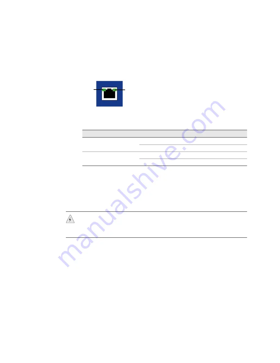
The Ethernet LEDs show the status of each Ethernet port. Figure 3 shows the
location of the LEDs on each Ethernet port.
Figure 3: Ethernet Port LEDs
Table 3 describes the Ethernet port LEDs.
Table 3: Ethernet Port LEDs
Reset Pinhole
The reset pinhole is a button that resets the device to its original default settings. To
use this button, insert a stiff wire (such as a straightened paper clip) into the
pinhole. See “Resetting the Device to Factory Defaults” on page 32 for more
information.
USB Port
The USB
port on the front panel of an SSG 140 device accepts a universal serial bus
(USB) storage device.
The USB ports let you transfer data such as device configurations, image keys, and
ScreenOS software between a USB storage device and the internal flash storage of
the security device. The USB ports support USB 1.1 and USB 2.0 specifications.
You can also log messages to a USB storage device. For more information about
logging, refer to the
Administration
volume of the
Concepts and Examples ScreenOS
Reference Guide.
To transfer data between a USB storage device and an SSG 140 device:
1.
Connect the USB storage device to either the upper or lower USB port on the
security device.
Name
Function
Color
State
Description
LINK
Link
Green
On steadily
Port is online.
Off
Port is offline.
TX/RX
Activity
Green
Blinking
Port is receiving data.
Off
Port might be on, but it is not receiving data.
LINK
TX/RX
WARNING:
Because resetting the device restores it to the original default
configuration, any new configuration settings are lost, and the firewall and all VPN
services become inoperative. We recommend that you save the device
configuration before resetting the device with the reset pinhole.