Juniper PTX3000 Quick Start Manual Download Page 24

Connect AC Power to the PTX3000 AC Power Supply Modules

Connect Nonredundant AC Power to the PTX3000 AC Power Supply
Modules on page 24

Connect Redundant AC Power to the PTX3000 AC Power Supply Modules on page 24

Connect Nonredundant AC Power to the PTX3000 AC Power Supply Modules

To connect nonredundant power, see

Connecting Nonredundant AC Power to the PTX3000

AC Power Supply Modules

in the

PTX3000 Packet Transport Router Hardware Guide

.

Connect Redundant AC Power to the PTX3000 AC Power Supply Modules

WARNING:

You must ground the packet transport router before connecting

the packet transport router to power.

To connect AC power to the PTX3000 packet transport router:

1.

Gather the following tools and parts:

Electrostatic discharge (ESD) grounding wrist strap

AC power cords, which should have a plug appropriate for your geographical location

2.

Attach an ESD grounding strap to your bare wrist, and connect the strap to one of the
ESD points on the chassis.

3.

Switch the power switch on the PSM faceplate to the standby position (

).

4.

Loosen the captive screw on the PSM.
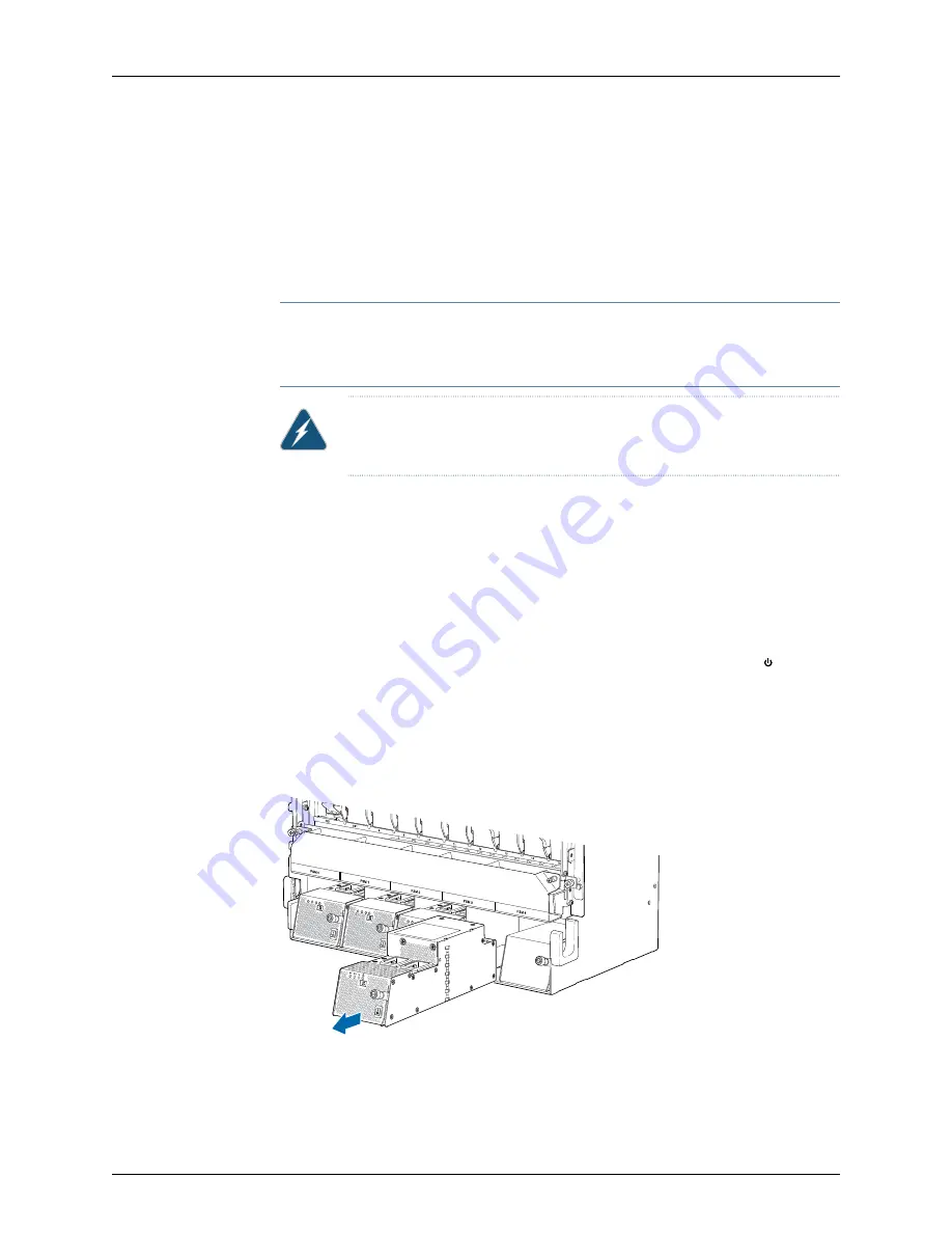
5.

Grasp the PSM, and pull it out to remove the PSM from the chassis (see

Figure 21 on page 24

).

Figure 21: Removing an AC PSM

g0

0

7

541

6.

Set the input switches for redundant power by setting both switches for input

1

and

2

to the on position (

ON

) as shown in

Figure 22 on page 25

.

Copyright © 2014, Juniper Networks, Inc.

24

PTX3000 Packet Transport Router Quick Start

Summary of Contents for PTX3000

Page 1: ...Packet Transport Router 5 Step 3 Install the PTX3000 Packet Transport Router Mounting Hardware 5 Install Cage Nuts If Needed 5 Install the Mounting Shelf 6 Step 4 Install the PTX3000 Packet Transport...

Page 2: ...acket Transport Router 26 Power On the AC Powered PTX3000 Packet Transport Router 27 Step 9 Install the Card Cage Screens on the PTX3000 Packet Transport Router 28 Step 10 Perform the PTX3000 Packet T...

Page 3: ...hassis is bolted to this pallet The shipping crate contains One accessory box the box to which this Quick Start is taped One Juniper Networks PTX3000 Packet Transport Router One Quick Start this docum...

Page 4: ...61 0 cm in front of the rack or cabinet is required However NEBS GR 63 recommends at least 30 in 76 2 cm in front of the rack or cabinet See Figure 1 on page 4 The rack or cabinet must have an adequat...

Page 5: ...lling or removing components from the chassis Blank panels to cover any slots not occupied by a component Step 2 Unpack the PTX3000 Packet Transport Router For detailed instructions on how to unpack t...

Page 6: ...17 1 U 29 9 in 76 0 cm 3 Install the Mounting Shelf Optionally you can install the mounting shelf before mounting the chassis in the rack To install the mounting shelf see Figure 2 on page 6 1 Align t...

Page 7: ...onto the lift making sure the packet transport router rests securely on the mechanical lift CAUTION Do not lift the packet transport router by using the handles on the front mounting flanges Use thes...

Page 8: ...ck repeat this procedure for each router See Figure 5 on page 11 and Figure 6 on page 12 for examples of multiple routers installed in a single rack Table 3 Mounting Hole Locations for Installing a Ch...

Page 9: ...Figure 3 Loading the PTX3000 onto the Lift 9 Copyright 2014 Juniper Networks Inc Install the Packet Transport Router By Using a Lift...

Page 10: ...Figure 4 Installing the PTX3000 in a Rack Copyright 2014 Juniper Networks Inc 10 PTX3000 Packet Transport Router Quick Start...

Page 11: ...lling Two PTX3000 Packet Transport Routers in a Rack Front View PTX3000 PTX3000 g007574 1 2 2 1 Lower chassis Upper chassis 11 Copyright 2014 Juniper Networks Inc Install the Packet Transport Router B...

Page 12: ...ns in the PTX3000 Packet Transport Router Hardware Guide for more information To ground the packet transport router 1 Gather the tools and parts required to ground the router Grounding cable which you...

Page 13: ...cable lug over the grounding points Figure 7 on page 13 7 Secure the grounding cable lug to the grounding points first with the washers then with the acorn nuts 8 Verify that the grounding cabling is...

Page 14: ...Attach an ESD grounding strap to your bare wrist and connect the strap to the ESD point on the chassis CAUTION During the initial installation before the chassis is grounded you must connect the wris...

Page 15: ...cable to a network device 1 To connect the packet transport router to external devices you need an electrostatic discharge ESD grounding wrist strap provided in the accessory box 2 Attach an ESD grou...

Page 16: ...e Module Reference You connect PICs to the network by plugging in network cable To connect cable to the PICs see Figure 11 on page 18 1 To connect the packet transport router to external devices you n...

Page 17: ...cover down Figure 13 on page 18 6 Arrange the cable in the cable management system to prevent it from dislodging or developing stress points Figure 14 on page 19 Secure the cable so that it is not su...

Page 18: ...Figure 11 Connecting PIC Cables Figure 12 Upper Cable Management System Figure 13 Lower Cable Management System Copyright 2014 Juniper Networks Inc 18 PTX3000 Packet Transport Router Quick Start...

Page 19: ...Supply Modules Connect Nonredundant DC Power to the PTX3000 DC Power Supply Modules on page 19 Connect Redundant DC Power to the PTX3000 DC Power Supply Modules on page 20 Connect Nonredundant DC Powe...

Page 20: ...t provide DC power lugs 2 Ensure that the voltage across the DC power source cable leads is 0 V and that there is no chance that the cable leads might become active during installation 3 Attach an ele...

Page 21: ...each DC PSM to feed A and input 2 on each DC PSM to feed B CAUTION You must ensure that power connections maintain the proper polarity The power source cables might be labeled and to indicate their po...

Page 22: ...C source power cables to input 1 and input 2 48V input terminals Figure 17 on page 22 and Figure 19 on page 23 Secure the negative DC source power cable lugs to the 48V input terminals Use a 7 16 in 1...

Page 23: ...rify that both input 1 and input 2 LEDs on the PSM faceplate are lit steadily green indicating that the inputs are receiving power 15 Reinstall the PSM into the chassis see Figure 20 on page 23 and ti...

Page 24: ...er To connect AC power to the PTX3000 packet transport router 1 Gather the following tools and parts Electrostatic discharge ESD grounding wrist strap AC power cords which should have a plug appropria...

Page 25: ...cated power feed derived from feed B This configuration provides the commonly deployed A B feed redundancy for the system For example you can connect input 1 on each AC PSM to feed A and input 2 on ea...

Page 26: ...ering off a power supply you must wait at least 60 seconds before powering it on again 1 Verify that the power supply modules PSMs are fully inserted in the chassis and that the captive screw on the f...

Page 27: ...ansport Router Hardware Guide After powering on a power supply you must wait at least 60 seconds before powering it off 8 Verify that the OK LED on the PSM faceplate is lit steadily and that the LED i...

Page 28: ...AC PSM faceplate is lit steadily indicating that power supply is correctly installed functioning properly and providing power to the DC outputs 10 On the external management device connected to the R...

Page 29: ...initial configuration use a device attached to the CON port For more information about the configuration statements in this procedure see the Junos OS Administration Library for Routing Devices To com...

Page 30: ...ser Configure System Attributes For more information about configuring the backup routing and static routes see the Junos OS Administration Library for Routing Devices To configure system attributes 1...

Page 31: ...hin the routing table edit root host set routing options static route remote subnet next hop destination IP retain no readvertise 7 Configure the telnet service at the edit system services hierarchy l...

Page 32: ...xxxxxx SECRET DATA name server 192 168 1 1 login user user uid 2001 class super user authentication encrypted password xxxxxxxxxxx SECRET DATA services telnet syslog user any emergency file messages a...

Page 33: ...ding the necessary configuration statements Then commit the changes to activate them edit root host commit synchronize 4 Exit configuration mode edit root host exit Exiting configuration mode root hos...

Page 34: ...Other services should be performed by authorized service personnel only Read the installation instructions before you connect the packet transport router to a power source Before installing the packet...

Page 35: ...an result in serious physical injury Compliance Statements for NEBS The equipment is suitable for installation as part of the Common Bonding Network CBN The equipment is suitable for installations in...

Page 36: ...uniper Networks has designed an online self service portal called the Customer Support Center CSC that provides you with the following features Find CSC offerings http www juniper net customers suppor...

Page 37: ...registered trademarks of Juniper Networks Inc in the United States and other countries The Juniper Networks Logo the Junos logo and JunosE are trademarks of Juniper Networks Inc All other trademarks...

Reviews: