J4350 and J6350 Services Router Getting Started Guide
1.
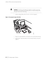
Take the following steps if you have not already done so:
a.
Attach an electrostatic discharge (ESD) grounding strap to your bare wrist
and connect the strap to the ESD point on the chassis, or to an outside
ESD point if the router is disconnected from earth ground. For more
information about ESD, see the Getting Started Guide for your router.
b.
Press and release the power button to power off the router. Wait for
the
POWER
LED to turn off.
c.
Unplug the power cord or cable from the power source receptacle.
d.
Remove the screws from the sides and top of the chassis that secure
the cover to the chassis.
e.
Slide the cover off the chassis.
2.
Remove the DRAM module from its electrostatic bag.
3.
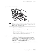
To open the empty DRAM socket, press the plastic ejectors on both sides
(see Figure 46).
4.
Grasp the DRAM module by the edges, being careful not to touch any electrical
components.
5.
Pressing firmly on both ends, push the module into the socket until the ejectors
click into the closed position (see Figure 46).
6.
Slide the cover onto the chassis.
7.
Replace and tighten the screws on the sides and top of the chassis that secure
the cover to the chassis.
8.
Replace the power cord or cable.
9.
Press and release the power button to power on the router. Verify that the
POWER
LED lights steadily after you press the power button.
10.
To view the DRAM configuration and verify that it was installed correctly,
issue the
show chassis routing-engine
command, described in the
JUNOS System
Basics and Services Command Reference
. This command shows the total
memory installed.
Replacing Power System Components
The power cords on all Services Routers are replaceable.
You can replace AC or DC power supplies in any Services Router. You can also add
a second power supply to the J6350 Services Router that is of the same type
as the first (either AC or DC).
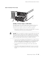
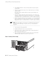
The power supplies are located at the right rear of the chassis (see Figure 3 and
Figure 5). Each power supply provides power to all components in the router. The
158
Replacing Hardware Components
Summary of Contents for J4350
Page 14: ...J4350 and J6350 Services Router Getting Started Guide xiv Table of Contents...
Page 22: ...2 J series Overview...
Page 68: ...J4350 and J6350 Services Router Getting Started Guide 48 Field Replaceable PIMs...
Page 75: ...Services Router User Interface Overview Figure 25 J Web Layout Using the J Web Interface 55...
Page 88: ...J4350 and J6350 Services Router Getting Started Guide 68 Using the Command Line Interface...
Page 90: ...70 Installing a Services Router...
Page 100: ...J4350 and J6350 Services Router Getting Started Guide 80 Site Preparation Checklist...
Page 112: ...J4350 and J6350 Services Router Getting Started Guide 92 Powering a Services Router On and Off...
Page 144: ...J4350 and J6350 Services Router Getting Started Guide 124 Verifying Secure Web Access...
Page 162: ...142 Maintaining Services Router Hardware...
Page 194: ...J4350 and J6350 Services Router Getting Started Guide 174 Troubleshooting Hardware Components...
Page 204: ...184 J series Requirements and Specifications...
Page 220: ...J4350 and J6350 Services Router Getting Started Guide 200 ISDN RJ 45 Connector Pinout...
Page 267: ...Part 5 Index Index 247...
Page 268: ...248 Index...


